Steca Solarix MPPT 2010 Installation And Operating Instruction
Solar charge controller
Hide thumbs
Also See for Solarix MPPT 2010:

Related Manuals for Steca Solarix MPPT 2010


Summary of Contents for Steca Solarix MPPT 2010
- Page 1 Installation and operating instructions Solar charge controller Solarix MPPT 2010 730927 | Z03 | 1242 730927 | Z03 | 1242...
-
Page 2: Table Of Contents
Contents About these instructions ..............3 Applicability ....................3 Users .......................3 1.3. Description of symbols ................3 Safety ....................3 Proper usage...................3 Improper usage ..................3 General safety instructions ..............4 Other risks ....................4 Behaviour in the case of faults ...............4 Description ..................5 Functions ....................5 Structure ....................6 LED displays ....................7 Installation ..................7 4.1. -
Page 3: About These Instructions
About these instructions These operating instructions are part of the product. X Read these operating instructions carefully before use, X keep them over the entire lifetime of the product, X and pass them on to any future owner or user of this product. Applicability This manual describes the installation, function, operation and maintenance of the solar charge controller. -
Page 4: General Safety Instructions
General safety instructions X Follow the general and national safety and accident prevention regulations. X Never alter or remove the factory plates and identification labels. X Keep children away from PV systems. X Never open the device. Other risks Danger of fire and explosion X Do not use the solar charge controller in dusty environments, in the vicinity of solvents or where inflammable gases and vapours can occur. -
Page 5: Description
Description Functions The solar charge controller • monitors the battery voltage, • controls the charging process, • controls the connection/disconnection of loads connected to the load output. This optimises battery use and significantly extends its service life. Solarzellen konv. La A battery charging algorithm protects the battery from harmful states. -
Page 6: Structure
the module voltage and string size. The module voltage can deviate signifi- cantly from the battery voltage. 3.1.4 Notes on choosing suitable solar modules This solar charge controller has a maximum input voltage of 100 V. If this is exceeded even for a short time by the connected solar module, the solar charge controller will be damaged beyond repair and can never be used again. -
Page 7: Led Displays
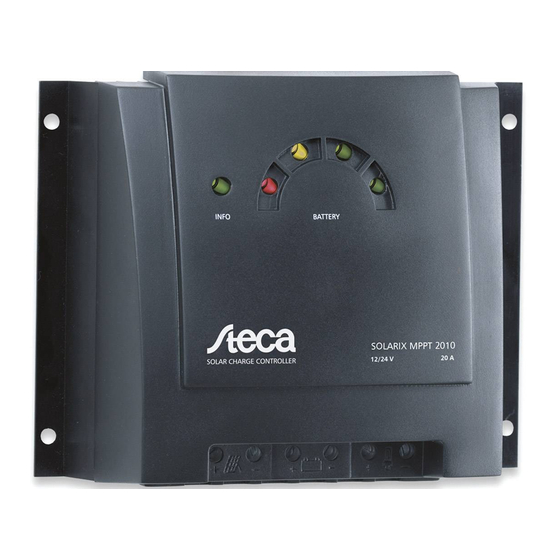
LED displays Status Meaning Info LED illuminates normal operation green flashes red a fault exists (see "Faults and remedies") Red LED flashes quickly battery empty when the battery continues to be discharged the deep-discharge deactivation is triggered flashes deep-discharge deactivation Yellow LED illuminates battery weak... -
Page 8: Mounting The Solar Charge Controller
4.1. Mounting the solar charge controller 4.1.1 Mounting location requirements • Do not mount the solar charge controller outdoors or in wet rooms. • Do not subject the solar charge controller to direct sunshine or other sources of heat. • Protect the solar charge controller from dirt and moisture. • Mount upright on the wall (concrete) on a non-flammable substrate. - Page 9 4.2.2 Connection WARNING Danger of explosion from sparking! Danger of electric shock! X At a voltage of > 75 V, particularly with regard to module open circuit volt- age (over the entire temperature range), the entire solar energy system must be installed with protection class II.
- Page 10 Loads connected in this manner must also be separately fused. Loads of this type can also be reliably connected via an additional output relay (e.g. Steca PA EV 200 A). X Label the load connection cables as a plus cable (L+) and a minus cable (L–).
- Page 11 X First connect the L+ load cable to the correct pole of the right pair of ter- minals on the solar charge controller (with the lamp symbol), then connect the L– cable. X Replace the load fuse or switch on the load. 4th step: final work X Fasten all cables with strain relief in the direct vicinity of the solar charge controller (clearance of approx.
-
Page 12: Operation
Operation The solar charge controller immediately begins operation once the battery is connected or the external fuse is inserted. The display of the solar charge controller shows the current operating mode. User intervention or user settings are not required. Protection functions The following integrated protection functions of the solar charge controller ensure that the battery is handled as gently as possible. -
Page 13: Faults And Remedies
Faults and remedies Fault Cause Remedy No display • Battery voltage too low Pre-charge the battery • The external fuse in the Replace the external fuse battery connection cable has blown. • Battery is not connected Unclamp all connections • Battery is defective Connect a (new) battery with the correct polarity Reconnect the solar module and loads... - Page 14 Load cannot be • Load output is switched The load output automati- operated off due to too low battery cally switched on again as voltage soon as the battery voltage lies within the permissible info LED flashes range Pre-charge the battery Equip loads directly con- red battery LED nected to the battery with...
- Page 15 Efficiency example: 100 % 99 % 98 % 97 % 96 % 95 % 94 % 93 % 92 % 91 % 90 % 15 W 40 W 85 W 120 W 200 W 280W 320 W 400 W 730927 | Z03 | 1242...
-
Page 16: Technical Data
Technical data MPPT 2010 Characterisation of the operating behaviour System voltage 12 V (24 V) Rated output 250 W (500 W) Max. efficiency > 98 % Own consumption 10 mA DC input side MPP voltage 15 V (30 V) < U <<... -
Page 17: Legal Guarantee
NOTE: Technical data that varies from the above is given on a device label. Subject to change without notice. Legal guarantee In accordance with German statutory regulations, there is a 2-year legal guar- antee on this product for the customer. The seller will remove all manufacturing and material faults that occur in the product during the legal guarantee period and affect the correct functioning of the product. - Page 18 730927 | Z03 | 1242...
- Page 19 730927 | Z03 | 1242...
- Page 20 730927...
Need help?
Do you have a question about the Solarix MPPT 2010 and is the answer not in the manual?
Questions and answers