Advertisement
Quick Links
CONTENTS
Page: 2. Introduction, How to Proceed, Usage Note, Disclaimer
3. System design – Diagram of a suggested system
4. Assembly notes – Important information about system elements
7. Connection & Operation – How to use the controller
14. Connectors, pinouts & jumpers – Essential connection information
26. Controller dimensions
27. Application notes
29. Troubleshooting
30. Specifications
31. Appendix I – Supported graphics modes table
34. Appendix II – RS-232 control protocols
51. Appendix III – Mapping definition
55. Appendix IV – Auto Color Gain
56. Appendix V – DV remote control unit work for SVX-1920
57. Appendix VI – Function description for de-interlacing mode AFM, TNR,
57. Appendix VII – PIP mix table
59. Appendix VIII - Network connection
59. Appendix IX – Panel wall support
60. Appendix X – RM-DN5 Assembly connection
61. Appendix XI – Specification for inverter Interface Board P/N 416040010-3
64. Appendix XII - Specification for audio add-on board P/N 416940020-3
66. Warranty, Caution & Limitation of Liability, Trademarks
67.Contact details
It is essential that these instructions are read and understood before connecting or
powering up this controller.
Specifications subject to change without notice
© Digital View Ltd – Doc Ver 2.7: 3 March, 2014 (SVX-1920_manual.doc)
Arrow.com.
Downloaded from
PC, DVI, HDMI, VIDEO INTERFACE CONTROLLER
FOR TFT PANEL
Model: SVX-1920
Part number : 41721003X-3 or up
[Firmware version : V0.50.00.00 or up]
INSTRUCTIONS
MADI, DCDi
1 of 67
Page
Advertisement

Related Manuals for digitalview 41721003X-3


Summary of Contents for digitalview 41721003X-3
- Page 1 PC, DVI, HDMI, VIDEO INTERFACE CONTROLLER FOR TFT PANEL Model: SVX-1920 Part number : 41721003X-3 or up [Firmware version : V0.50.00.00 or up] INSTRUCTIONS CONTENTS Page: 2. Introduction, How to Proceed, Usage Note, Disclaimer 3. System design – Diagram of a suggested system 4.
- Page 2 Support on screen marker Support video wall connection Ordering information : Controller Part number Ordering part number SVX-1920 P/N 41721003X-3 P/N 4172100XX-3 HOW TO PROCEED Ensure you have all parts & that they are correct, refer to: • Connection diagram Controller Solution Generator Full web resource matching controllers &...
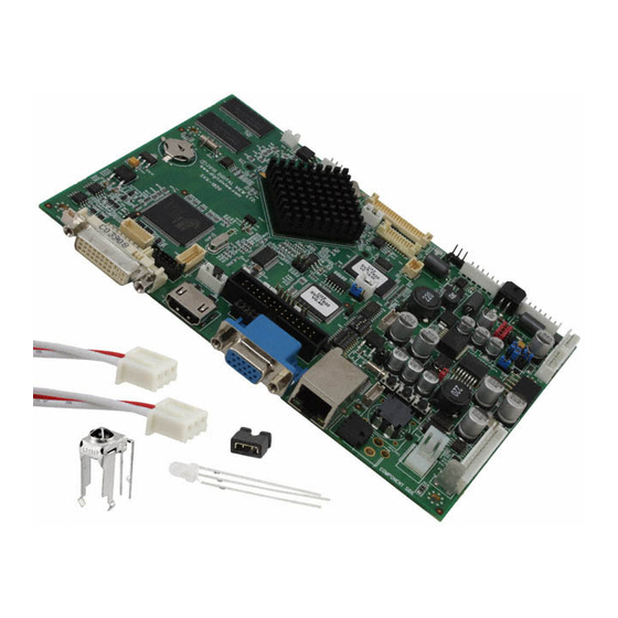
- Page 3 SYSTEM DESIGN A typical LCD based display system utilizing this controller is likely to comprise the following: Summary: LCD panel LCD controller card, SVX-1920 LCD signal cable (use for LVDS panel) Inverter for backlight (if not built into LCD) Inverter cable Function controls Function controls cable Status LED (optional)
- Page 4 ASSEMBLY NOTES This controller is designed for monitor and custom display projects using 1920x1200 or 1920x1080 or 1600x1200 or 1680x1050 or 1440x900 or 1366x768 or 1280 x 1024 or 1024 x 768 or 800x600 or 640x480 resolution TFT panels with a VGA, SVGA, WXGA, XGA, SXGA, UXGA or WUXGA signal input.
- Page 5 12. External panel power output : User for specific panel model. 13. Panel control signal : Use for specific panel model. 14. Audio add-on board P/N 416940020-3: Provide the interface for the audio add-on board P/N 416940020-3 to be connected. The audio add-on board gives the audio input and output signal connection. The volume can be controlled by the OSD menu on the controller.
- Page 6 • Controller Mounting: It is recommended that a clearance of at least 10mm is provided above and 5mm below the controller when mounted. Additionally consideration should be given to: • Electrical insulation. • Grounding. • EMI shielding. • Cable management. Note: It is important to keep panel signal cables apart from the inverter & backlight cables to prevent signal interference.
- Page 7 10. Power supply & Controller: Plug the DC 12V/24V power in to the connector PP5 or PP2/3. You can consider to use DigitalView mating power cable P/N 426013800-3, 160mm for PP5 connection. 11. External panel power input : Plug power cable : P/N 426013700-3 for external panel power input (3.3 (max 7A) / 5V (max 7A) / 12V (max 5A) / 18V (max3.5))
- Page 8 LCD DISPLAY SYSTEM SETTINGS NOTE: By way of explanation the following refers to a set of sample buttons that may be obtained as an option. In addition to power on/off and connection for backlight brightness the controller provides an On Screen Display of certain functions which are controlled by 5 momentary type buttons (analog VR type) or 8 momentary type buttons (digital type): Controls Analog VR type...
- Page 9 OSD functions Picture : Volume Increase/decrease volume level, total: 100 steps Brightness Increase/decrease panel brightness level, total: 100 steps Contrast Increase/decrease panel contrast level, total: 100 steps Saturation Increase/decrease saturation, total: 100 steps Hue ** Increase/decrease Hue level, total: 100 steps Sharpness* Increase/decrease sharpness, total: 30 steps Backlight...
- Page 10 Source : Select the input video signal Main Port Change 4 HDMI HD/SD SDI 1 HD/SD SDI 2 Composite 1 Composite 2*** S-Video 1 S-Video 2*** Component 1 Component 2*** PIP Port change4 PIP Off / Composite 1 / S-Video 1 / Component 1 / DVI / HDMI / HD/SD SDI 1 / HD/SD SDI PIP Size4: Off / PIP Size/ 1~18 / Size by Size / Size by Size Tall...
- Page 11 Composite 1 Composite 2 S-Video 1 S-Video 2 Component 1 Component 2 The corresponding input port name display on OSD menu will disappear once setting “OFF”. Auto Power : OFF / ON ON – Enable soft power off function if absence of input signals OFF –...
- Page 12 Blue Gain : Red Offset : Green Offset : Blue Offset : Reset to Defaults : Resume to the default values 6500K Red Gain : Green Gain : Blue Gain : Red Offset : Green Offset : Blue Offset : Reset to Defaults : Resume to the default values 8000K Red Gain :...
- Page 13 - Light Detector : : Enable ambient light detector function by using KIT 70220-3 Default Setting 4 Reset to Factory Defaults 4 (Activate when JC1 position 4 sets open) Are you sure ? Yes/No Reset to Factory Defaults with (Color Temp.) 4 (Activate when JC1 position 4 sets open) Are you sure ? Yes/No Save Current Settings as Calibrated Values 4 (Activate when JC1 position 2 sets closed) Are you sure ? Yes/No...
- Page 14 CONNECTORS, PINOUTS & JUMPERS The various connectors are: Summary: Connectors Purpose Description Second RS-232 serial control JST 6-way, B6B-XH-A (Matching type : XHP-6) Alternate DVI connector JST BM20B-SRDS (Matching type : SHDR-20V-S-B) Panel control signal connector Hirose 10-pin, DF20G-10DP-1V (Matching type : DF20A-10DS-1C) Alternate HDMI connector JST BM20B-SRDS (Matching type : SHDR-20V-S-B)
- Page 15 (Matching video cable P/N 426000600-3) CNV5 Auxiliary video input Header pin 13x2 (Matching video cable P/N 426000800-3) Ethernet for network connection RJ45 connector Additional panel power output Hirose 20-pin, DF13-20DP-1.25 (Matching type : DF13-20DS-1.25C) Panel signal for LVDS panel Hirose 40 pin, DF13-40DP-1.25DSA (Matching type : DF13-40DS-1.25C) Infra-Red sensor connector JST 3-way, B3B-XH-A...
- Page 16 Summary: Jumpers setting Purpose Note On board +3.3V logic power enable 1-2 & 3-4 closed, factory set, do not remove Panel power voltage select See panel voltage setting table 1 CAUTION: Incorrect setting can damage panel Panel power voltage select See panel voltage setting table 1 CAUTION: Incorrect setting will cause panel damage...
- Page 17 PP2/PP3, PP5 3.3V 3V3 closed 1-3 & 2-4 1-3 & 2-4 12VDC 5V closed 1-3 & 2-4 1-3 & 2-4 OPEN 1-3 & 2-4 5-7 & 6-8 CAUTION: Incorrect setting can damage panel & controller Input voltage via PP2/PP3, PP5 Panel Voltage Jumper on board 3.3V...
- Page 18 Input voltage via Panel Voltage Jumper on board 3.3V OPEN 3-5 & 4-6 1-3 & 2-4 OPEN 3-5 & 4-6 1-3 & 2-4 3.3 / 5 / 12 / 18VDC* OPEN 3-5 & 4-6 3-5 & 4-6 OPEN 3-5 & 4-6 3-5 &...
- Page 19 Table 2 : DIP Switch selection – SW3 Pos #1 Pos #2 Pos #3 Pos.#4 Description Panel resolution For WUXGA panels LG LM260WU1-SLB1 1920x1200 LG LM240WU2-SLA1 1920x1200 Sharp LQ445D3LZ19 1920x1080 Samsung LTA460H2-L02 1920x1080 Sharp LQ170M1LZ04 1920x1200 Samsung LTA700HH-LH1 (1 trial testing) 1920x1080 Samsung LTA700HH-LH1 (2 trial testing)
- Page 20 Table 3 : DIP switch selection – SW4 Pos. # Function Description Reserved Panel pixel format OFF : Double Pixel ON : Single Pixel Panel selection ON : LVDS panel OFF : Reserved LVDS data mapping select If SW4 position 5 = OFF (8 bit) (Refer to Table 2) OFF : Mapping B ON : Mapping A...
- Page 21 CN1 – Slave RS-232 serial control: JST B6B-XH-A (Matching type : XHP-6) SYMBOL DESCRIPTION SDATA Reserved SCLK Reserved RS-232 Tx data Ground RS-232 Rx data CN2 – Alternate DVI connector: JST BM20B-SRDS (Matching type : SHDR-20V-S-B) SYMBOL DESCRIPTION Digital Ground Digital Ground TMDS Clock+ /RXC...
- Page 22 CN7 - Audio connector: DIL socket header 5x2 right angle [OPERATE UNDER 12VDC POWER INPUT ENVIRONMENT] SYMBOL DESCRIPTION Audio board logic power supply, +5V VOLSEL0 Reserved VOLSEL1 Reversed TUNAUDSEL Reserved CLK/CNT Reserved Ground +12V/+24V Audio board power supply, +12V/+24V No connection No connection Ground CN8 –...
- Page 23 BVR_WIP Backlight brightness VR pin WIP BVR_B Backlight brightness VR pin B (470Ω resistor to +5V Vcc) Ground MENU OSD menu button -/LEFT OSD -/Left button +/RIGHT OSD +/Right button SEL_DN OSD Select down button SEL_UP OSD Select up button No connection The VR for brightness depends on the inverter.
- Page 24 VDD (3,3V/5V) Panel power supply (3,3V/5V) Ground Ground Ground Ground Ground Ground Ground Ground VDD +12V / +18V Panel power supply (+12V/18V) (selected by JA3, JA5 & JA6) VDD +12V / +18V Panel power supply (+12V/18V) (selected by JA3, JA5 & JA6) VDD +12V / +18V Panel power supply (+12V/18V) (selected by JA3, JA5 &...
- Page 25 Reserved for monitor ID bit 2 (grounded) DGND Digital ground AGND Analog ground red AGND Analog ground green AGND Analog ground blue DDC_5V +5V power supply for DDC (optional) DGND Digital ground Reserved for monitor ID bit 0 (grounded) DDC_SDA DDC serial data HS_IN Horizontal sync or composite sync, input...
- Page 26 Ready-made 3D Pro-E (SLDPRT) drawing files - Save time and effort for your system volumetric analysis design. Includes jpg file previews. Please go to download at http://www.digitalview.com/products/svx-1920-lcd-controller The maximum thickness of the controller is 17.65mm with or without video add-on board (measured from bottom of PCB to top of components, including any underside components &...
- Page 27 APPLICATION NOTES USING THE CONTROLLER WITHOUT BUTTONS ATTACHED This is very straightforward: • Firstly setup the controller/display system with the buttons. With controls attached and display system active make any settings for colour, tint and image position as required then switch everything off. •...
- Page 28 Design Guideline for making VR circuitry : Signal description / Notes : 1) R1 : 470ohm on board 2) RPOT is an external potentiometer (in-line dip style) that can be plugged directly into CNC1 pins 3,4,5. RPOT must be supplied / installed by user. 3) BVR_B : Voltage tapped from “top”...
- Page 29 TROUBLESHOOTING General A general guide to troubleshooting a flat panel display system it is worth considering the system as separate elements, such as: Controller (jumpers, PC settings) Panel (controller, cabling, connection, panel, PC settings) Backlight (inverter, cabling, backlight tubes) Cabling Computer system (display settings, operating system) Through step by step cross checking with instruction manuals and a process of elimination to isolate the problem it is usually possible to clearly identify the problem area.
- Page 30 SPECIFICATIONS Panel compatibility Compatible with 1920x1200, 1920x1080, 1680x1050, 1600x1200, 1440x900 1366x768, 1280x1024, 1024x768, 800x600 & 640x480 resolutions of TFT LCD panels. A specified BIOS and some factory adjustment may be required for individual panel timings. No. of colours Up to 3 x 10 bit providing 1.06 billion colours. Panel power DC 3.3V, 5V, 12V, 18V Panel signal...
- Page 31 APPENDIX I – SIGNAL SUPPORT MODE TABLE ARGB (P1) PORT : Mode Resolution Clk [MHz] Horizontal Vertical Sync Mode freq [KHz] freq [Hz] T_70 720x400 28.322 31.469 70.087 Digital Separate Sync 70Hz T_70 720x400 28.322 31.469 70.087 Sync On Green 70Hz V_60 640x480...
- Page 32 X_60 1024x768 65.000 48.363 60.004 Sync On Green 60Hz X_60 1024x768 65.000 48.363 60.004 Composite Sync 60Hz X_70 1024x768 75.000 56.476 70.069 Digital Separate Sync 70Hz X_70 1024x768 75.000 56.476 70.069 Sync On Green 70Hz X_70 1024x768 75.000 56.476 70.069 Composite Sync 70Hz X_75...
- Page 33 COMPOSITE, S-VIDEO & COMPONENT VIDEO INPUT PORT : System Resolution Horizontal freq Vertical freq [KHz] [Hz] NTSC 720x480i 15.7 NTSC 4.43 720x480i 15.7 720x576i 15.6 PAL M 720x576i 15.6 SECAM 720x576i 15.6 Specifications subject to change without notice 33 of 67 ©...
- Page 34 The RS-232 program can be custom-made to fit for application or it can be used the serial control program, like Accessport, Telix or Serial Utility program developed by DigitalView. Please contact your local support for information. Specifications subject to change without notice 34 of 67 ©...
- Page 35 1. Commands to implement switch mount control buttons Function Command Description Remark Menu button 0xf7 Menu button pressed Button equivalent Select-down 0xfa Select-down button pressed Button equivalent button Select-up button 0xfb Select-up button pressed Button equivalent Right/+ button 0xfc Right/+ button pressed Button equivalent Left/- button 0xfd...
- Page 36 nnnn | “+” | “-” | value/increment/decrement (In PC mode only) “?” Query Image V position 0x87, Set img_vpos = Image vertical position. nnnn | “+” | “-” | value/increment/decrement (In PC mode only) “?” Query Sharpness 0x8a, Set sharpness = Sharpness.
- Page 37 “0” | “1” | Disable/ Enable “0x42,0x31”- Composite “?” | Query “0x42,0x32”- Composite 2 ”o” Valid Source query “0x43,0x31”- S-video “0x43,0x32”- S-video 2 “0x44,0x31”- Component “0x44,0x32”- Component 2 “0x45,0x31”- HDSDI “0x45,0x32”- HDSDI2 “0x46,0x31”- DVI “0x48,0x31” HDMI Source Layout 0x9a, Select source layout = Query: Single, PIP, PBP, PBPT “0”- Single...
- Page 38 “D” – PIP Swap “E” – Aspect Ratio “G” – Hue “H” – Backlight “I” – Auto Picture Setup “K” – PIP ON/OFF*** Hotkey 2 0xa0, “2”, Set Hotkey 2 = “1” – volume. value “2” – brightness. “r” | “R” | Reset “3”...
- Page 39 “0x48,0x31” HDMI Zoom level 0xa8, Set Zoom level = Zoom level. nnnn | “+” | “-” | value/increment/decrement “r” | “R” | Reset Min : 0x30 0x30 0x30 0x30 “?” Query (Default) Max : 0x30 0x30 0x41 0x33 Zoom H position 0xa9, Set Zoom_hpos = Zoom window horizontal...
- Page 40 temperature nn | “+” | “-” | value/increment/decrement “r” | “R” | Reset Range : “9””C”-“F””F” “?” Query Default : “E””C” “m” Maximum query *1 “n” Minimum query *1 c – reference by Color “i” , ss, c, nn Set, Source, Temperature Temperature Group, value *1 ss - reference by Input main...
- Page 41 c=2 for color Blue) 0xbf, “R” | “r” Set user gamma curve to linear “1” 0xbf, mm, c, nn Set gamma data for color c “nn” = gamma data index mm. (If c= 3, then gamma data for red, green & blue will be set at the same time.) Query External 0xcb, “2”...
- Page 42 260Hz : “1”,”0”,”4” 280Hz : “1”,”1”,”8” 300Hz : “1”,”2”,”C” 320Hz : “1”,”4”,”0” 340Hz : “1”,”5”,”4” 360Hz : “1”,”6”,”8” 380Hz : “1”,”7”,”C” 400Hz : “1”,”9”,”0” 420Hz : “1”,”A”,”4” 440Hz : “1”,”B”,”8” Backlight Invert 0xe7 Set On or Off “0” – Off “0”...
- Page 43 CenterMarker “0xee”, “0x43” “0”- Off “0” |”1” Center Marker Off / Center “1”- On Marker On AspectMarker “0xee”, “0x44” Preliminary “0”- 4:3 “0” |”1” 4:3 /16:9 “1”- 16:9 Marker “0xee”, “0x45” Preliminary “0”- 0% Background “0” |”1” |”2” |”3” 0% /25%/50%/95% “1”- 25% Transparency “2”- 50%...
- Page 44 Function Command Description Acknowledge (if enabled) Send Display 0xF1, “S” – Send Command Mark ”S” | “S” = “0x53 or 0x73” “Text” – Character ”0x21” | ”0x40” ASCII “0x21,0x40,0x60,0x7E” ”0x60” | ”0x7E” Return “1” Return “ 0x31” “1” - successful. e.g Send Display Mark RS232 Code: “0xF1 0x53 0x21”...
- Page 45 Soft Power On/Off 0xc8, Soft power “0” – Turn off the LCD power and “0” | “1” | off/on backlight. Turn off memory “?” query controller, Power down DVI Power down ADC, Power down Fclk PLL “1” – Turn on the unit Query video input 0xc9 Query the status of the...
- Page 46 “E” – Checksum Error Wide Screen 0xd9, “0” – Normal Mode Mode Selection “0” | “1”| “2” Wide Screen Mode “1” – 1280x768 “r” | “R” Reset “2” – 1366x768 “?” Query ScreenMarker “0xee”, “0x42” “0”- Off “0” |”1” Screen Marker Off / Screen Marker On “1”- On CenterMarker “0xee”, “0x43”...
- Page 47 The following commands for sending texts by using RS-232 command. Function Command Description Acknowledge (if enabled) Send Line 0xF0, “S” = “0x53 or 0x73” “S” – Send Command |”S” |”LL”|”TEXT”| Send command “LL” – Line Number “0x0A” ------------------------------------------- “Text” – Character Return “1”...
- Page 48 Left offset 0xF0, “O” = “0x4F or 0x6F” “O” – Left Offset Command |”O” |”SSS”| Set Left Offset command “SSS”- Offset Value (pixels) Return “nnn” ------------------------------------------- “nnn”- Return Value(pixels) “SSS” = “0x30,0x30,0x30~ 0x33,0x46,0x46” Offset Value (Rang 000~3ff) e.g Set Left Offset = 100 pixels ( 0x64 (HEX)) RS232 Code: “0xF0 0x4F 0x30 0x36 0x34”...
- Page 49 Display Mark Command Function Command Description Acknowledge (if enabled) Send Display Mark 0xF1, ”S” | “S” = “0x53 or 0x73” “S” – Send Command ”0x21” | ”0x40” ASCII “0x21,0x40, 0x21 : Full size cell black block ”0x60” | ”0x7E” 0x60,0x7E 0x40 : Full size cell white block ”0x22”...
- Page 50 Set Display Mark background Transparency value is 8 RS232 Code: “0xF1 0x42 0x38” Return Code: “0xF1 0x42 0x38 0x38” # - Effective on V0.45.00.01 or later revision. Bi-directional “0xee”, “0x64” Send command “0xee 0x64” – Send Command communication “0x7B”| Start Text Command “0x7B”...
- Page 51 The RS-232 command strings sent in one time can support up to 380 bytes via CN8 port The RS-232 command string sent in one time can support up to 50 bytes via CN1 or J1 port. n = 1-byte ascii-coded hex number, e.g., parameter value of 0x1 is represented by “1” (0x31). mn or nn = 2-byte ascii-coded hex number, e.g., parameter value of 0x1e is represented by “1”, “e”...
- Page 52 Appendix III – Mapping definition • Definition of Mapping A : Specifications subject to change without notice 52 of 67 © Digital View Ltd – Doc Ver 2.7: 3 March, 2014 (SVX-1920_manual.doc) Page Arrow.com. Arrow.com. Arrow.com. Arrow.com. Arrow.com. Arrow.com. Arrow.com. Arrow.com.
- Page 53 • Definition of Mapping B : Specifications subject to change without notice 53 of 67 © Digital View Ltd – Doc Ver 2.7: 3 March, 2014 (SVX-1920_manual.doc) Page Arrow.com. Arrow.com. Arrow.com. Arrow.com. Arrow.com. Arrow.com. Arrow.com. Arrow.com. Arrow.com. Arrow.com. Arrow.com. Arrow.com. Arrow.com.
- Page 54 • Definition of VESA : Specifications subject to change without notice 54 of 67 © Digital View Ltd – Doc Ver 2.7: 3 March, 2014 (SVX-1920_manual.doc) Page Arrow.com. Arrow.com. Arrow.com. Arrow.com. Arrow.com. Arrow.com. Arrow.com. Arrow.com. Arrow.com. Arrow.com. Arrow.com. Arrow.com. Arrow.com. Arrow.com.
- Page 55 • Definition of JEIDA : Specifications subject to change without notice 55 of 67 © Digital View Ltd – Doc Ver 2.7: 3 March, 2014 (SVX-1920_manual.doc) Page Arrow.com. Arrow.com. Arrow.com. Arrow.com. Arrow.com. Arrow.com. Arrow.com. Arrow.com. Arrow.com. Arrow.com. Arrow.com. Arrow.com. Arrow.com. Arrow.com.
- Page 56 The reference pattern can be downloaded at : http://www.digitalview.com/support/downloads/TestPattern_1280.BMP This reference pattern is for 1280x1024 resolution and it needs to set your ARGB input source to 1280x1024 resolution before performing the Auto Color Gain function. The position of the black vertical bar in the pattern at the right side is important.
- Page 57 Appendix V – DV remote control unit work for SVX-1920 P/N 559000106-3 : DigitalView remote control unit (without DV logo silk screen printing) P/N 559000105-3 : DigitalView remote control unit (with DigitalView logo silk screen printing) BUTTON FUNCTION POWER BUTTON Soft power ON/OFF button.
- Page 58 Appendix VI – Function description for de-interlacing mode AFM, TNR, MADI, DCDi AFM = Auto Film Mode : It is a frame based method which used for the input ODD and EVEN fields have a fixed relation between each other, such as static image, 3:2 pull down mode. If two fields are correctly merged, it can get the best quality.
- Page 59 Connect the SVX-1920 to the network and ensure power is on. • Use the IP-50 IP Locator utility available from the IP-50 web-page. http://www.digitalview.com/media/downloads/IPLocator.zip (Windows only) • Double click on the IP address in the IP Locator window, it will open the SVX-1920 browser page in your default browser.
- Page 60 Appendix X – RM-DN5 Assembly connection SVX-1920 add “RM-DN5 Assembly” menu on Programming mode for selection the DN5 standard version or Serenity E1.16.10 version. Procedure : 1. Set closed on JC1 position 7 to enable this function Set closed on JC1 position 7 2.
- Page 61 Appendix XI - Inverter Interface Board P/N 416040010-3 [OPERATE UNDER 12VDC POWER INPUT ENVIRONMENT] The Inverter interface board provides interface to drive up the high current consumption panel inverter in excess of 3.5A. This board enables current of up to 8 Amps to be managed safely while retaining the capability for inverter dimming and management of the inverter enable signal according to VESA DPMS standards.
- Page 62 Illustrated Diagram PP1 - 12VDC power supply – input, Power header 4 ways 0.156” pitch DESCRIPTION +12VDC +12VDC Ground Ground PP2 – Alternate 12VDC power supply – input, Terminal Block 2 poles DESCRIPTION +12VDC +12VDC Ground Ground PP3 – 12VDC power supply to controller – Output, Power header 2 ways, 0.156” pitch DESCRIPTION +12VDC Ground...
- Page 63 CNB3 – Inverter interface to backlight inverter, JST B8B-XH-A SYMBOL DESCRIPTION VLCD12 Panel power VLCD12 Panel power Ground Ground VLCD12 Panel power BLCTRL Backlight on/off control signal BVR_WIP Backlight brightness VR pin WIP BVR_A Backlight brightness VR pin A Specifications subject to change without notice 63 of 67 ©...
- Page 64 Appendix XII - Audio Add-on Board P/N 416940020-3 [OPERATE UNDER 12VDC POWER INPUT ENVIRONMENT] The Audio add-on board P/N 416940020-3 design for connection with DV controllers on the audio connector CN7. It provides audio input ports and output port for sound amplification. Electrical Specification : Supply Voltage : +12V, +5V Supply current : 35mA for +12V, 6mA for +5V...
- Page 65 CN3 : Controller interface connector Pin Number Description Left trimpot chip select Right trimpot chip select Trimpot serial data Trimpot serial clock Digital Ground +12V Audio input left Audio input right Audio Ground Mechanical Drawing : Specifications subject to change without notice 65 of 67 ©...
- Page 66 WARRANTY The products are warranted against defects in workmanship and material for a period of three (3) year from the date of purchase provided no modifications are made to it and it is operated under normal conditions and in compliance with the instruction manual.
- Page 67 Digital View Inc. 18440 Technology Drive Building 130 Morgan Hill, California, 95037 Tel: (1) 408-782 7773 Fax: (1) 408-782 7883 Sales: ussales@digitalview.com EUROPE Digital View Ltd. The Lake House Knebworth Park Herts, SG3 6PY Tel: +44-(0)20-7631-2150 Fax: Fax: +44-(0)20-7631-2156 Sales: uksales@digitalview.com...
Need help?
Do you have a question about the 41721003X-3 and is the answer not in the manual?
Questions and answers