Advertisement
Quick Links
CONTENTS
Page: 2. Introduction, How to Proceed, Usage Note, Disclaimer
2. System design – Diagram of a suggested system
3. Assembly notes – Important information about system elements
5. Connection & Operation – How to use the controller
8. Connectors, pinouts & jumpers – Essential connection information
16. Controller dimensions
17. Application notes
19. Troubleshooting
20. Specifications
21. Appendix I – Graphic Mode Support Table
22. Appendix II – RS-232 control protocols
24. Appendix III – Mapping definition
26. Warranty, Caution & Limitation of Liability, Trademarks
27. Contact details
It is essential that these instructions are read and understood before connecting or
powering up this controller.
HARSH ENVIRONMENT
PC, DVI INTERFACE CONTROLLER
FOR TFT PANEL
Model: HE-1400
Part number : 41710013X-3
INSTRUCTIONS
1
Advertisement

Related Manuals for digitalview HE-1400


Summary of Contents for digitalview HE-1400
- Page 1 HARSH ENVIRONMENT PC, DVI INTERFACE CONTROLLER FOR TFT PANEL Model: HE-1400 Part number : 41710013X-3 INSTRUCTIONS CONTENTS Page: 2. Introduction, How to Proceed, Usage Note, Disclaimer 2. System design – Diagram of a suggested system 3. Assembly notes – Important information about system elements 5.
- Page 2 A typical LCD based display system utilising this controller is likely to comprise the following: Summary: LCD panel LCD controller card, HE-1400 LVDS cable (for connection with LVDS panel) TTL cable (for connection with TTL panel) Inverter for CCFT backlight (if not built into LCD)
- Page 3 ASSEMBLY NOTES This controller is designed for monitor and custom display projects using 1366 x 768, 1280 x 1024 or 1280 x 768 or 1024 x 768 or 800x600 or 640x480 resolution TFT panels with a VGA, SVGA, XGA, SXGA signal input. The following provides some guidelines for installation and preparation of a finished display solution.
- Page 4 • PC Graphics Output: A few guidelines: • Signal quality is very important, if there is noise or instability in the PC graphics output this may result in visible noise on the display. • Refer to graphics modes table in specifications section for supported modes. •...
- Page 5 VGA cable & Controller: Plug the VGA cable to the connector P1 on the controller board. Power supply & Controller: Plug the DC 12V power in to the connector PP2. You can consider to use DigitalView mating power cable P/N 426013800-3, 160mm.
- Page 6 LCD DISPLAY SYSTEM SETTINGS NOTE: By way of explanation the following refers to a set of sample buttons that may be obtained as an option. In addition to power on/off and connection for backlight brightness the controller provides an On Screen Display of certain functions which are controlled by 5 momentary type buttons (analog VR type) or 8 momentary type buttons (digital type): Controls Analog VR type...
- Page 7 Adjust red color level Press – or + (- +) Total :128 steps Adjust green color level Press – or + (- +) Total : 128 steps Adjust blue color level Press – or + (- +) Total : 128 steps Press SEL UP/DN button to select item Set the color temperature to 4200K Set the color temperature to 5000K...
- Page 8 CONNECTORS, PINOUTS & JUMPERS The various connectors are: Summary: Connectors Purpose Description LVDS panel signal Hirose 40-pin, DF13-40DP-1.25DSA (Mating type : DF13-40DS-1.25C) TTL panel signal Hirose 40-pin, DF20G-40DP-1V (Mating type : DF20A-40DS-1C) TTL Panel signal Hirose 50-pin, DF20G-50DP-1V (Mating type : DF20A-50DS-1C) Serial control (for firmware JST 6-way, B6B-XH-A (Mating type : XHP-6)
- Page 9 Summary: Jumpers setting Purpose Note On board +5V power enable 1-2 & 3-4 closed, factory set, do not remove Panel power voltage select See panel voltage setting table 1 CAUTION: Incorrect setting will cause panel damage Panel power voltage select See panel voltage setting table 1 CAUTION: Incorrect setting will cause panel damage Backlight inverter on/off control –...
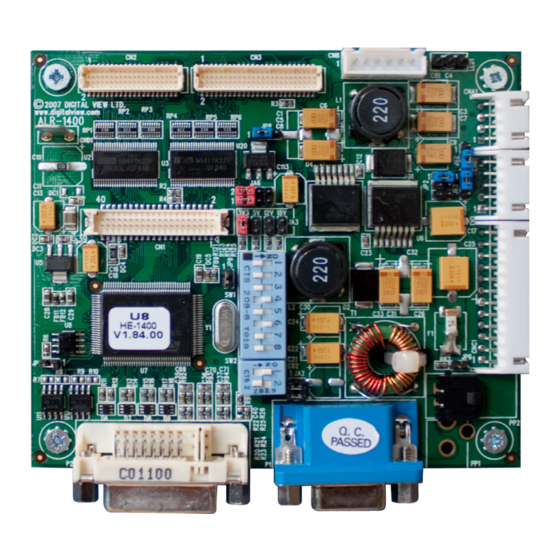
- Page 10 JA3 & JA6 location on board : (Please pay attention to the jumper settings on JA3 & JA6 which are red in color on board)
- Page 11 Sharp LQ104S1DG21 Sharp LQ121S1DG41 Sharp LQ084S3DG01 Toshiba LTM12C289 For VGA panel Sharp LQ104V1DG21 Sharp LQ10D368 Sharp LQ104V1DG51 For additonal and recent added panels, see HE-1400 panel support table at http://www.digitalview.com/controllers/csg.php Pos #5 Pos #6 Pos #7 Description Reserved Reserved SXGA...
- Page 12 CN1 – Panel connector: Hirose, DF13A-40DP-1.25DSA (Matching type : DF13-40DS-1.25C) SYMBOL DESCRIPTION TXA0+ Positive differential LVDS data bit A0 TXA0- Negative differential LVDS data bit A0 TXA1+ Positive differential LVDS data bit A1 TXA1- Negative differential LVDS data bit A1 Reserved Reserved TXA2+...
- Page 13 No connection Even data bit B0 Even data bit B1 Even data bit B2 Even data bit B3 Even data bit B4 Even data bit B5 Even data bit B6 Even data bit B7 Ground Ground Dot clock No connection CN3 –...
- Page 14 CN8 – RS-232 serial control: JST B6B-XH-A (Matching type : XHP-6) SYMBOL DESCRIPTION SDATA Reserved SCLK Reserved RS-232 Tx data Ground RS-232 Rx data CNA1 - Auxiliary power output: JST B4B-XH-A (Matching type : XHP-4) SYMBOL DESCRIPTION AUX POWER +12V DC, 500mA max Ground Ground AUX 5V...
- Page 15 P1 - Analog VGA input – DB-15 way high density 3 row SYMBOL DESCRIPTION Red, analog Green, analog Blue analog Reserved for monitor ID bit 2 (grounded) DGND Digital ground AGND Analog ground red AGND Analog ground green AGND Analog ground blue DDC_5V +5V power supply for DDC (optional) DGND...
- Page 16 CONTROLLER DIMENSIONS The maximum thickness of the controller is 15.8mm (measured from bottom of PCB to top of components, including any underside components & leads). We recommend clearances of: • 5mm from bottom of PCB - if mounting on a metal plate we also recommend a layer of suitable insulation material is added to the mounting plate surface.
- Page 17 APPLICATION NOTES USING THE CONTROLLER WITHOUT BUTTONS ATTACHED This is very straightforward by following the steps below : • Firstly setup the controller/display system with the buttons. With controls attached and display system active make any settings for colour and image position as required then switch everything off. •...
- Page 18 Design Guideline for making VR circuitry : Signal description / Notes : 1) R1 : 470ohm on board 2) RPOT is an external potentiometer (in-line dip style) that can be plugged directly into CNC1 pins 3,4,5. RPOT must be supplied / installed by user. 3) BVR_B : Voltage tapped from “top”...
- Page 19 TROUBLESHOOTING General A general guide to troubleshooting a flat panel display system it is worth considering the system as separate elements, such as: Controller (jumpers, PC settings) Panel (controller, cabling, connection, panel, PC settings) Backlight (inverter, cabling, backlight tubes) Cabling Computer system (display settings, operating system) Through step by step cross checking with instruction manuals and a process of elimination to isolate the problem it is usually possible to clearly identify the problem area.
- Page 20 SPECIFICATIONS Panel compatibility 1366x768, 1280x1024, 1280x768, 1024 x 768, 800x600, 640x480 TFT LVDS or TTL LCD’s support. No. of colours Up to 3 x 8 bit providing 16.7 million colours. Vertical refresh rate SXGA, XGA, SVGA, VGA resolution up to 60Hz. Dot clock (pixel clock) maximum 135 MHz Graphics formats...
- Page 21 Appendix I – Graphic Mode Support Table Mode Resolution Clk [MHz] Horizontal Vertical Sync Mode freq [KHz] freq [Hz] E1_70 640x350 25.175 31.469 70.087 Digital Separate Sync 70Hz E2_70 640x400 25.175 31.469 70.087 Digital Separate Sync 70Hz V_60 640x480 25.175 31.469 59.940 Digital Separate Sync...
- Page 22 The OSD function can be controlled through sending the RS-232 protocol. The RS-232 program can be custom-made to fit for application or it can be used the program provided by Digitalview on request. Please contact your local sales for informations.
- Page 23 Green level for 0xb5, Set the level of the green Green level for selected colour selected colour channel for the selected colour temperature. temperature nn | “+” | “-” | temp. = Range : “8””0”-“F””F” “r” | “R” | value/increment/decrement Default : “F””F”...
- Page 24 Appendix III – Mapping definition • Definition of Mapping A :...
- Page 25 • Definition of Mapping B :...
- Page 26 The manufacturer’s liability for damages to customer or others resulting from the use of any product supplied hereunder shall in no event exceed the purchase price of said product. TRADEMARKS The following are trademarks of Digital View Ltd: • Digital View • HE-1400...
- Page 27 Digital View Ltd 19 th Floor Tai Tung Building 8 Fleming Road, Wanchai Hong Kong Tel: (852) 2861 3615 Fax: (852) 2520 2987 Sales: hksales@digitalview.com EUROPE Digital View Ltd. 6 Marylebone Passage, London, W1W 8EX Tel: +44-(0)20-7631-2150 Fax: +44-(0)20-7631-2156 Sales: uksales@digitalview.com...
Need help?
Do you have a question about the HE-1400 and is the answer not in the manual?
Questions and answers