Table of Contents
Advertisement
Quick Links
PC, DVI, DISPORT PORT, HDMI, VIDEO INTERFACE CONTROLLER
CONTENTS
Page: 2. Introduction, How to Proceed, Usage Note, Disclaimer
It is essential that these instructions are read and understood before connecting or
powering up this controller.
Specifications subject to change without notice
© Digital View Ltd – Doc Ver 3.01: 13 April, 2016
Arrow.com.
Downloaded from
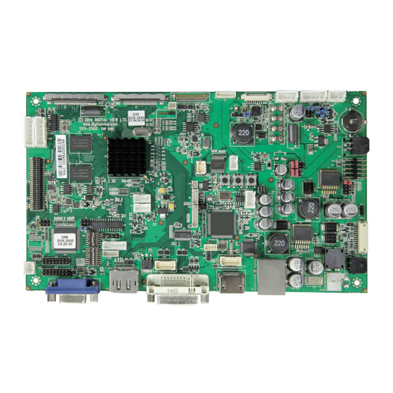
Model: SVX-2560
Part number : 41747002X-3 or up
3. System design – Diagram of a suggested system
4. Assembly notes – Important information about system elements
7. Connection & Operation – How to use the controller
14. Connectors, pinouts & jumpers – Essential connection information
28. Controller dimensions
29. Application notes
31. Troubleshooting
32. Specifications
33. Appendix I – Supported graphics modes table
37. Appendix II – RS-232 control protocols
48. Appendix III – Mapping definition
52. Appendix IV – Auto Color Gain
53. Appendix V – DV remote control unit work for SVX-2560
54. Appendix VI – PIP mix table
55. Appendix VII - Network connection
56. Warranty, Caution & Limitation of Liability, Trademarks
57. Contact details
58. Revision history
FOR TFT PANEL
INSTRUCTIONS
1 of 58
Page
Advertisement
Table of Contents

Related Manuals for digitalview SVX-2560


Summary of Contents for digitalview SVX-2560
- Page 1 37. Appendix II – RS-232 control protocols 48. Appendix III – Mapping definition 52. Appendix IV – Auto Color Gain 53. Appendix V – DV remote control unit work for SVX-2560 54. Appendix VI – PIP mix table 55. Appendix VII - Network connection 56.
- Page 2 Introduction Designed for LCD monitor and other flat panel display applications, the SVX-2560 is a feature rich interface controller for : TFT (active matrix) LCD panels of 2560x1600, 2560x1440, 1920x1920, 1920x1200, 1920x1080, 1920x480, 1680x1050, 1600x1200, 1600x900, 1440x900, 1366x768, 1280x1024, 1280x800, 1280x768 1024x768, 1024x600, 800x600, 800x480 and 640x480 resolutions.
-
Page 3: System Design
SYSTEM DESIGN A typical LCD based display system utilizing this controller is likely to comprise the following: Specifications subject to change without notice 3 of 58 © Digital View Ltd – Doc Ver 3.01: 13 April, 2016 Page Arrow.com. Arrow.com. Arrow.com. -
Page 4: Assembly Notes
ASSEMBLY NOTES This controller is designed for monitor and custom display projects using 2560x 1600, 2560x1440, 1920x1920,1920x1200 or 1920x1080 or 1600x1200 or 1680x1050 or 1440x900 or 1366x768 or 1280 x 1024 or 1024 x 768 or 800x600 or 640x480 resolution TFT panels with a VGA, SVGA, WXGA, XGA, SXGA, UXGA or WUXGA signal input. The following provides some guidelines for installation and preparation of a finished display solution. - Page 5 12. External panel power output : User for specific panel model. 13. Panel control signal : Use for specific panel model. 14. SPDIF Audio output : This port support SPDIF audio output from the HDMI / Displayport audio source inputted. The audio output follows with the input source selected (HDMI / Displayport).
- Page 6 Cable management. Note: It is important to keep panel signal cables apart from the inverter & backlight cables to • prevent signal interference. Heat & Ventilation: Heat generated from other sources, for example the backlight of a very high brightness panel •...
-
Page 7: Connection And Operation
10. Power supply & Controller: Plug the DC 12V/24V power in to the connector PP5 or PP2. You can consider to use DigitalView mating power cable P/N 426013800-3, 160mm for PP5 connection. 11. External panel power input : Plug power cable : P/N 426013700-3 for external panel power input (3.3 (max 7A) / 5V (max 7A) / 12V (max 5A) / 18V (max3.5)) - Page 8 LCD DISPLAY SYSTEM SETTINGS NOTE: By way of explanation the following refers to a set of sample buttons that may be obtained as an option. In addition to power on/off and connection for backlight brightness the controller provides an On Screen Display of certain functions which are controlled by 5 momentary type buttons (analog VR type) or 8 momentary type buttons (digital type): Controls Analog VR type...
- Page 9 OSD functions Picture : Brightness Increase/decrease panel brightness level, total: 100 steps Contrast Increase/decrease panel contrast level, total: 100 steps Saturation Increase/decrease saturation, total: 100 steps Hue ** Increase/decrease Hue level, total: 100 steps Sharpness* Increase/decrease sharpness, total: 30 steps Backlight Backlight brightness adjustment (Functions when light detector sets OFF)
- Page 10 Source : Select the input video signal Main Port Change 4 HDMI Display Port Component 1 PIP Port change4 PIP Off / VGA/ DVI / HDMI / Display Port / Component 1 PIP Size4: Off / PIP Size 1~18 / Size by Size / Size by Size Tall The PIP capability on display input sources refer to Appendix VII –...
- Page 11 ON – Enable soft power off function if absence of input signals OFF – Disable soft power function Anti Image Retention : Anti Image Retention : Method : Flash / Pixel Shift / Horizontal Pan / Vertical Pan Flash : Flashing the screen Pixel Shift : Image shift pixel by pixel around the screen Horizontal Pan : Display a pattern moving horizontally on screen.
- Page 12 Vertical pan : : Pan the image vertically Factory Reset Note : Freeze state will be cleared when you using zoom function. Color Temperature 4 5000K Red Gain : Green Gain : Blue Gain : Red Offset : Green Offset : Blue Offset : Reset to Defaults : Resume to the default values 6500K...
- Page 13 - Backlight Frequency : 100 ~ 440Hz in a step of 20 - Light Detector : : Enable ambient light detector function by using KIT 70220-3 - Min Backlight Level : 0 ~ 50% : Default the minimum backlight adjustment. Default Setting 4 4 4 4 Reset to Factory Defaults 4 4 4 4 (Activate when JC1 position 4 sets open) Are you sure ? Yes/No...
-
Page 14: Connectors, Pinouts & Jumpers
CONNECTORS, PINOUTS & JUMPERS The various connectors are: Summary: Connectors Purpose Description Second RS-232 serial control JST 6-way, B6B-XH-A (Matching type : XHP-6) On board internal connector for DVI JST BM20B-SRDS (Matching type : SHDR-20V-S-B) (Matching extend cable P/N 426302900-3) Reserved for external temperature JST 3-way, B3B-XH-A or compatible (Matching type : XHP-3) - Page 15 LVDS panel signal output 2 JAE FI-RE51S-HF (Matching type : FI-RE51HL) Display port output for panel I-PEX 20455-030E-12 (Matching type : I-PEX 20454-030T) connection Panel power output for Disport port Molex 53261-0871 (Matching type : Molex 51021-0800) interface panel use. Reserved for Digital interface for SDI / DIL Header 25x2, 1.27x2.54 SMT Video mux board (AVD-1000)
- Page 16 Table 1 : Panel voltage setting table : Input voltage via PP2 / PP5 Panel Voltage Jumper on board 3.3V 3V3 closed 1-3 & 2-4 1-3 & 2-4 5V closed 1-3 & 2-4 1-3 & 2-4 12VDC OPEN 1-3 & 2-4 5-7 &...
- Page 17 Input voltage via Input voltage via PP2 / PP5 Panel Voltage Jumper on board 3.3V OPEN 3-5 & 4-6 1-3 & 2-4 OPEN 3-5 & 4-6 1-3 & 2-4 3.3 / 5 / 12 / 12V / 24VDC 18VDC* OPEN 3-5 &...
- Page 18 Table 2 : DIP Switch selection – SW3 GROUP 1 Pos #1 Pos #2 Pos #3 Pos.#4 Description Panel resolution For WUXGA panels LG LM260WU1-SLB1 1920x1200 LG LM240WU2-SLA1 1920x1200 Sharp LQ445D3LZ19 1920x1080 Samsung LTA460H2-L02 1920x1080 Sharp LQ170M1LZ04 1920x1200 Samsung LTA700HH-LH1 (1 trial testing) 1920x1080 Samsung LTA700HH-LH1 (2...
- Page 19 GROUP 2 Pos #1 Pos #2 Pos #3 Pos #4 Pos #5 Pos #6 Pos #7 Panel resolution Sharp LQ235D1LW03 120Hz 1920x1080 LG LM265SQ1-SLA1(Tested) 1920x1920 LG LM270WQ1-SDE3 2560x1440 LG LM300WQ6-SL01 2560x1600 Pos. #8 Video lock ON – Disable : Always fix the output be 60Hz. OFF –...
- Page 20 CN1 – Slave RS-232 serial control: JST B6B-XH-A (Matching type : XHP-6) SYMBOL DESCRIPTION EXT_MSTR2_SCL Reserved EXT_MSTR2_SDA Reserved RS-232 Tx data Ground RS-232 Rx data CN2 – Alternate DVI connector: JST BM20B-SRDS (Matching type : SHDR-20V-S-B) SYMBOL DESCRIPTION Digital Ground Digital Ground TMDS Clock+ /RXC...
- Page 21 CN7 - 2x5 right angled header (Matching audio add-on board P/N 416940020-3 & Audio extend cable P/N 426009700-3) SYMBOL DESCRIPTION Audio board logic power supply, +5V VOLSEL0 Reserved VOLSEL1 Reversed TUNAUDSEL Reserved CLK/CNT Reserved Ground +12V/+24V Audio board power supply, +12V/+24V No connection No connection Ground...
- Page 22 CNV2 – Component (YPbPr) video input connector: JST 6-way, B6B-PH-K (Matching type : XHP-6) SYMBOL DESCRIPTION A_Y1 Luma in / Green in Ground A_Pb1 Pb in / Blue in Ground A_Pr 1 Pr in / Red in Ground IR1 – Infra-Red sensor connector: JST B3B-XH-A (Matching type : XHP-3) SYMBOL DESCRIPTION Ground...
- Page 23 J3 – LVDS output connector: JAE FI-RE51S-HF (Matching type : JAE FI-RE51HL) SYMBOL DESCRIPTION VLCD_HV Panel power supply (+12V / 18V) (selected by JA3, JA5 & JA6) VLCD_HV Panel power supply (+12V / 18V) (selected by JA3, JA5 & JA6) VLCD_HV Panel power supply (+12V / 18V) (selected by JA3, JA5 &...
- Page 24 J4 – Display port output for panel connector: I-PEX 20455-030E-12 (Matching type : I-PEX 20454-030T) SYMBOL DESCRIPTION Ground Ground Ground Ground VLCD_LV Panel power supply (3,3V/5V) (selected by JA3, JA5 & JA6) VLCD_LV Panel power supply (3,3V/5V) (selected by JA3, JA5 & JA6) VLCD_LV Panel power supply (3,3V/5V) (selected by JA3, JA5 &...
- Page 25 J6 – Reserved for Digital interface for SDI / Video mux board (AVD-1000) interface connector: 2 x 25 ways, 2.54x1.27 header (This connector function is not implemented yet) (Matching ribbon cable : P/N 426171100-3) SYMBOL DESCRIPTION Ground Ground CbCr0 (Input) CbCr0 (Input) Y0 (Input) Y0 (Input)
- Page 26 LED1 – Status LED connector: 3-pin header DESCRIPTION Green LED pin (anode) LED pin common (cathode) Red LED pin (anode) P1 - Analog VGA in - 15 way connector SYMBOL DESCRIPTION Red, analog Green, analog Blue analog Reserved for monitor ID bit 2 (grounded) DGND Digital ground AGND...
- Page 27 CLK- TMDS Clock– No connection SCL (I²C Serial Clock for DDC) SDA (I²C Serial Data Line for DDC) CEC/GND Ground +5 V Power (max 50 mA) HPDET Hot Plug Detect P4 – Display Port input SYMBOL DESCRIPTION ML_Lane 0 (p) Lane 0 (positive) Ground ML_Lane 0 (n)
-
Page 28: Controller Dimensions
Ready-made 3D Pro-E (SLDPRT) drawing files - Save time and effort for your system volumetric analysis design. Includes jpg file previews. Please go to download at http://www.digitalview.com/products/svx-2560-lcd-controller The maximum thickness of the controller is 18.9mm with or without video add-on board (measured from bottom of PCB to top of components, including any underside components &... -
Page 29: Application Notes
APPLICATION NOTES USING THE CONTROLLER WITHOUT BUTTONS ATTACHED This is very straightforward: Firstly setup the controller/display system with the buttons. With controls attached and display system active make any • settings for color, tint and image position as required then switch everything off. Remove the control switches, the 12-way (CNC1) cable. - Page 30 Design Guideline for making VR circuitry : Signal description / Notes : 1) R1 : 470ohm on board 2) RPOT is an external potentiometer (in-line dip style) that can be plugged directly into CNC1 pins 3,4,5. RPOT must be supplied / installed by user. 3) BVR_B : Voltage tapped from “top”...
-
Page 31: Troubleshooting
TROUBLESHOOTING General A general guide to troubleshooting a flat panel display system it is worth considering the system as separate elements, such Controller (jumpers, PC settings) Panel (controller, cabling, connection, panel, PC settings) Backlight (inverter, cabling, backlight tubes) Cabling Computer system (display settings, operating system) Through step by step cross checking with instruction manuals and a process of elimination to isolate the problem it is usually possible to clearly identify the problem area. -
Page 32: Specifications
SPECIFICATIONS Panel compatibility Compatible with 2560x1600, 2560x1440, 1920x1920, 1920x1200, 1920x1080, 1920x480, 1680x1050, 1600x1200, 1600x900, 1440x900, 1366x768, 1280x1024, 1280x800, 1280x768 1024x768, 1024x600, 800x600, 800x480 and 640x480 resolutions of TFT LCD panels. A specified BIOS and some factory adjustment may be required for individual panel timings. -
Page 33: Appendix I - Signal Support Mode Table
APPENDIX I – SIGNAL SUPPORT MODE TABLE ARGB (P1) PORT : Mode Resolution Clk [MHz] Horizontal Vertical Sync Mode freq [KHz] freq [Hz] V_60 640x480 25.175 31.469 59.940 Digital Separate Sync 60Hz V_60 640x480 25.175 31.469 59.940 Composite Sync 60Hz V_72 640x480 31.500... - Page 34 WXGA 1280x768 79.5 47.776 59.87 Sync On Green 60Hz WXGA 1360x768 85.5 47.712 60.015 Digital Separate Sync 60Hz WXGA 1360x768 85.5 47.712 60.015 Sync On Green 60Hz WXGA 1366x768 87.75 47.852 59.964 Digital Separate Sync 60Hz WXGA+ 1440x900 88.75 55.469 59.901 Digital Separate Sync 60Hz...
- Page 35 HDMI input port : Resolution 640x480 60Hz 640x480 72Hz 640x480 75Hz 800x600 56Hz 800x600 60Hz 800x600 72Hz 800x600 75Hz 1024x768 60Hz 1024x768 70Hz 1024x768 75Hz 1280x768 60Hz 1280x1024 60Hz 1280x1024 75Hz 1366x768 60Hz 1400x1050 60Hz 1440x900 60Hz 1600x900 60Hz 1600x1200 60Hz 1680x1050 60Hz 1920x1200 60Hz 2560x1600 60Hz...
- Page 36 Component video port : Mode 720p60 720p59.94 720p50 720p30 720p29.97 720p24 720p23.976 1080p30 1080p29.97 1080p25 1080p24 1080p23.98 Specifications subject to change without notice 36 of 58 © Digital View Ltd – Doc Ver 3.01: 13 April, 2016 Page Arrow.com. Arrow.com. Arrow.com.
-
Page 37: Appendix Ii - Rs-232 Control Protocols
The RS-232 program can be custom-made to fit for application or it can be used the serial control program, like Accessport, Telix or Serial Utility program developed by DigitalView. Please contact your local support for information. Specifications subject to change without notice 37 of 58 ©... - Page 38 1. Commands to implement switch mount control buttons Function Command Description Remark Menu button 0xf7 Menu button pressed Button equivalent Select-down 0xfa Select-down button pressed Button equivalent button Select-up button 0xfb Select-up button pressed Button equivalent Right/+ button 0xfc Right/+ button pressed Button equivalent Left/- button 0xfd...
- Page 39 “?” Query Scaling Mode 0x8c, Set graphic image scaling mode Image expansion on/off. “0” | “1” | “2” | “3” | “0” – 1:1 “9” | “A” | value “1” – fill screen “B” | “C” | “D” | Reset “2”...
- Page 40 “8” – freeze "9" - PIP “B” – No function "D" - PIP Swap “E” – Aspect Ratio “G” – Hue “H” – Backlight “I” – Auto Picture Setup "K" - PIP ON/OFF Hotkey 2 0xa0, “2”, Set Hotkey 2 = “2”...
- Page 41 change depends on input resolution. Colour 0xb3, Select colour temperature = Main selected. temperature select value “0” – 9300K. “r” | “R” | Reset “1” – 8000K.(Default) “?” Query “2” – 6500K. “3” – 5000K “4” - User Red level for 0xb4, Set the level of the red channel Red level for selected colour...
- Page 42 seconds. OSD turn off 0xbd Turn off the OSD. “0” – fail. “1” – successful. Query External 0xcb, “2” Check External Menory 24c256 “0” – Not Installed Memory “1” – Installed “?” – Not Support Query Revision 0xcb, “3” Read Revision Number “nn”...
- Page 43 Red Offset for 0xe8, Set the Offset of the red channel Red Offset for selected colour selected colour for the selected colour temp. = temperature. temperature nn | “+” | “-” | value/increment/decrement “r” | “R” | Reset Range : “8””0”-“7””F” “?”...
- Page 44 280Hz : "0""0" ~ "3""2" 300Hz : "0""0" ~ "3""2" 320Hz : "0""0" ~ "3""2" 340Hz : "0""0" ~ "3""0" 360Hz : "0""0" ~ "3""0" 380Hz : "0""0" ~ "3""0" 400Hz : "0""0" ~ "3""1" 420Hz : "0""0" ~ "3""1" 440Hz : "0""0"...
- Page 45 YY= Version Number ZZ= Customer Number Query PCBA 0xcb, “1” Read PCBA number “nnnnn” = PCBA number number SVX-2560= “41747” Reset to Factory 0xce Reset all parameters to “1” – successful. Defaults default value Reset to Factory 0xcf Reset all parameters for all “1”...
- Page 46 e.g Clear Line 1 RS232 Code: “0xF0 0x43 0x30 0x31” Return Code: “0xF0 0x43 0x30 0x31 0x30 0x31” Text Window 0xF0, “H” = “0x48 or 0x68” “H” – Horizontal Position Horizontal Position |”H” |”ss”| ------------------------------------------ command Return “nn” --“nn” = “0x30,0x30~0x46,0x46” “ss”...
- Page 47 On or Off “N” Disable ---------------------- Background Return “n” “N” = “0x30~0x31” “0” Turn Off Text Overlay Background “n”- Return Value Set background Transparency value is 8 RS232 Code: “0xF0 0x51 0x31” Return Code: “0xF0 0x51 0x31 0x31” Please set the "Background Transparency” and "Left offset" commands before the "Send Line" command.
-
Page 48: Appendix Iii - Mapping Definition
Appendix III – Mapping definition Definition of Mapping A : • Specifications subject to change without notice 48 of 58 © Digital View Ltd – Doc Ver 3.01: 13 April, 2016 Page Arrow.com. Arrow.com. Arrow.com. Arrow.com. Arrow.com. Arrow.com. Arrow.com. Arrow.com. Arrow.com. - Page 49 Definition of Mapping B : • Specifications subject to change without notice 49 of 58 © Digital View Ltd – Doc Ver 3.01: 13 April, 2016 Page Arrow.com. Arrow.com. Arrow.com. Arrow.com. Arrow.com. Arrow.com. Arrow.com. Arrow.com. Arrow.com. Arrow.com. Arrow.com. Arrow.com. Arrow.com. Arrow.com.
- Page 50 Definition of VESA : • Specifications subject to change without notice 50 of 58 © Digital View Ltd – Doc Ver 3.01: 13 April, 2016 Page Arrow.com. Arrow.com. Arrow.com. Arrow.com. Arrow.com. Arrow.com. Arrow.com. Arrow.com. Arrow.com. Arrow.com. Arrow.com. Arrow.com. Arrow.com. Arrow.com. Arrow.com.
- Page 51 Definition of JEIDA : • Specifications subject to change without notice 51 of 58 © Digital View Ltd – Doc Ver 3.01: 13 April, 2016 Page Arrow.com. Arrow.com. Arrow.com. Arrow.com. Arrow.com. Arrow.com. Arrow.com. Arrow.com. Arrow.com. Arrow.com. Arrow.com. Arrow.com. Arrow.com. Arrow.com. Arrow.com.
-
Page 52: Appendix Iv - Auto Color Gain
RGB values are then stored in the controller and are unaffected by the Reset Factory Defaults function. The reference pattern can be downloaded at : http://www.digitalview.com/support/downloads/TestPattern_1280.BMP This reference pattern is for 1280x1024 resolution and it needs to set your ARGB input source to 1280x1024 resolution before performing the Auto Color Gain function. -
Page 53: Appendix V - Dv Remote Control Unit Work For Svx-2560
Appendix V – DV remote control unit work for SVX-2560 P/N 559000106-3 : DigitalView remote control unit (without DV logo silk screen printing) P/N 559000105-3 : DigitalView remote control unit (with DigitalView logo silk screen printing) BUTTON FUNCTION POWER BUTTON Soft power ON/OFF button. -
Page 54: Appendix Vi - Pip Mix Table
Appendix VI – PIP mix table HDMI Display Port Component PIP \ MAIN (P1) (P2/CN2) (P3/CN5) (P4) (CNV2) VGA (P1) DVI (P2/CN2) HDMI (P3/CN5) Display Port (P4) Component (CNV2) Specifications subject to change without notice 54 of 58 © Digital View Ltd – Doc Ver 3.01: 13 April, 2016 Page Arrow.com. -
Page 55: Appendix Vii - Network Connection
Use the IP Locator utility available from the IP-60 web-page. • http://www.digitalview.com/media/downloads/IPLocator.zip (Windows only) Double click on the IP address in the IP Locator window, it will open the SVX-2560 • browser page in your default browser. Alternatively copy the IP address into your browser address line. -
Page 56: Warranty
TRADEMARKS The following are trademarks of Digital View Ltd: Digital View • SVX-2560 • Specifications subject to change without notice 56 of 58 © Digital View Ltd – Doc Ver 3.01: 13 April, 2016 Page Arrow.com. -
Page 57: Contact Details
Digital View Inc. 18440 Technology Drive Building 130 Morgan Hill, California, 95037 Tel: (1) 408-782 7773 Fax: (1) 408-782 7883 Sales: ussales@digitalview.com EUROPE Digital View Ltd. The Lake House Knebworth Park Herts, SG3 6PY Tel: +44-(0)20-7631-2150 Fax: Fax: +44-(0)20-7631-2156 Sales: uksales@digitalview.com... - Page 58 Revision History Date Rev No. Page Summary 9 Dec 2014 1.00 First issued 13 March 2014 2.00 Features added for up to P/N 417470022-3 version. 29 Jan 2016 3.00 - Add "Image Orientation" function on OSD menu page. - Correct typo in the "Connector" table for CN2 - JST BM20B-SRDS 18-19 Add the definition of SW3 position 8 for video...
Need help?
Do you have a question about the SVX-2560 and is the answer not in the manual?
Questions and answers