Table of Contents
Advertisement
Quick Links
PC & VIDEO INTERFACE CONTROLLER
FOR 1280 x 1024, 1024 x 768 RESOLUTIONS TFT LCD
CONTENTS
Page: 2. Introduction, How to Proceed, Usage Note, Disclaimer
3. System design – Diagram of a suggested system
4. Assembly notes – Important information about system elements
6. Connection & Operation – How to use the controller
12. Connectors, pinouts & jumpers – Essential connection information
18. Controller dimensions
19. Application notes
20. Troubleshooting
21. Specifications
24. Warranty, Caution & Limitation of Liability, Trademarks
25. Contact details
It is essential that these instructions are read and understood before connecting or
powering up this controller.
Model: SVP-1280
Part number : 4165100-XX
INSTRUCTIONS
1
Advertisement
Table of Contents

Related Manuals for digitalview SVP-1280


Summary of Contents for digitalview SVP-1280
- Page 1 PC & VIDEO INTERFACE CONTROLLER FOR 1280 x 1024, 1024 x 768 RESOLUTIONS TFT LCD Model: SVP-1280 Part number : 4165100-XX INSTRUCTIONS CONTENTS Page: 2. Introduction, How to Proceed, Usage Note, Disclaimer 3. System design – Diagram of a suggested system 4.
-
Page 2: How To Proceed
Introduction Designed for LCD monitor and other flat panel display applications the SVP-1280 controller provides an auto-input synchronization and easy to use interface controller for: TFT (active matrix) LCD panels of 1280x1024, 1024x768, 800x600 and 640x480 resolutions; Computer video signals of VGA, SVGA, XGA and SXGA standard. -
Page 3: System Design
A typical LCD based display system utilising this controller is likely to comprise the following: Summary: LCD panel LCD controller card, SVP-1280 LCD panel connector board for LCD signal cable (if necessary) LCD signal cables Inverter for backlight (if not built into LCD) -
Page 4: Assembly Notes
ASSEMBLY NOTES This controller is designed for monitor and custom display projects using 1280 x 1024 or 1024 x 768 resolution TFT panels with a VGA, SVGA, XGA or SXGA signal input. The following provides some guidelines for installation and preparation of a finished display solution. - Page 5 • Controller Mounting: It is recommended that a clearance of at least 10mm is provided above and 5mm below the controller when mounted. Additionally consideration should be given to: • Electrical insulation. • Grounding. • EMI shielding. • Cable management. Note: It is important to keep panel signal cables apart from the inverter & backlight cables to prevent signal interference.
-
Page 6: Connection And Operation
CONNECTION & OPERATION CAUTION: Never connect or disconnect parts of the display system when the system is powered up as this may cause serious damage. CONNECTION Connection and usage is quite straight forward (it is useful to have the relevant connection diagram available at this time): LCD panel &... - Page 7 LCD DISPLAY SYSTEM SETTINGS NOTE: By way of explanation the following refers to a set of sample buttons that may be obtained as an option. In addition to power on/off and connection for backlight brightness the controller provides an On Screen Display of certain functions which are controlled by 5 momentary type buttons (analog VR type) or 8 momentary type buttons (digital type): Controls Analog VR type...
- Page 8 Frequency and Phase : (DISPLAYED IN PC MODE ONLY) Frequency Adjust the image horizontal size Phase Fine tune the data sampling position (adjust image quality) Picture Type : Motion / Still Select still mode to getting a stable image in displaying still picture Video System : Select video system and input signals (DISPLAYED IN VIDEO MODE ONLY)
- Page 9 Language : Select OSD menu language display 1. English 2. Danish 3. Chinese Video source : Select the input video signal Analog RGB / Component Video / Composite Video / S-Video Utilities : User Setting : User Timeout : adjust the OSD menu timeout period in a step of 5 seconds DPMS : Disable / Enable the DPMS function Display Input...
- Page 10 RS-232 serial control (Baud rate = 2400 bps) The OSD function can be controlled through send HEX code with the following button mapping table. MENU 0xf7 Language 0x95 Scalar V Pan 0xb2 SEL_DN 0xfa Input Source 0x98 Color Temp 0xb3 SEL_UP 0xfb Source Priority...
-
Page 11: (Contrast) Button
FUNCTION POWER BUTTON Power ON/OFF button. (Standby mode) Use combined with digit keys to enable/disable the IR function. ATTENTION BUTTON SVP-1280 “Attention” + “1” MUTE BUTTON Switch to mute on/off mode. AV/TV BUTTON Use to select the input source. (RGB/Composite/S-Video/Component) Use to display the zoom menu. -
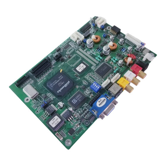
Page 12: Connectors, Pinouts & Jumpers
CONNECTORS, PINOUTS & JUMPERS The various connectors are: Summary: Connectors Purpose Description Panel signal Hirose 28-pin, DF11-28DP-2DSA (Matching type : DF11-28DS-2C) Panel signal Hirose 32-pin, DF11-32DP-2DSA (Matching type : DF11-32DS-2C) Panel signal Hirose 20-pin, DF11-20DP-2DSA (Matching type : DF11-20DS-2C) Audio board connector DIL socket header 5x2 right angle RS-232 serial control JST 6-way, B6B-XH-A... - Page 13 Summary: Jumpers setting Purpose Note On board +5V logic power enable 1-2 & 3-4 closed, factory set, do not remove On board +3.3V logic power enable 1-2 & 3-4 closed, factory set, do not remove Panel power voltage select 1-3 & 2-4 = +5V panel voltage (Factory set) CAUTION: Incorrect setting can damage panel 3-5 &...
- Page 14 CN2 – Panel connector: HIROSE DF11-28DP-2DSA (Matching type : DF11-28DS-2C) SYMBOL DESCRIPTION Ground Ground Even data bit R2 Odd data bit R2 Even data bit R3 Odd data bit R3 Even data bit R4 Odd data bit R4 Even data bit R5 Odd data bit R5 Even data bit G2 Odd data bit G2...
- Page 15 CN4 – Panel connector: HIROSE DF11-20DF-2DSA (Matching type : DF11-20DS-2C) SYMBOL DESCRIPTION Ground Ground No connection No connection Even data bit R0 (LSB) Odd data bit R0 (LSB) Even data bit R1 Odd data bit R1 Even data bit G0 (LSB) Odd data bit G0 (LSB) Even data bit G1 Odd data bit G1...
- Page 16 CNB1 – Backlight inverter connector: JST B5B-XH-A (Matching type : XHP-5) SYMBOL DESCRIPTION Ground VBKL +12VDC, backlight power supply BLCTRL On/Off control (enable) – see JB2 & JB3 BVR_WIP Brightness VR – WIP BVR_A Brightness VR A CNC1 – Function controls connector: JST B12B-XH-A (Matching type : XHP-12) SYMBOL DESCRIPTION PSWIN...
- Page 17 IR1 – Infra-Red sensor connector: JST B3B-XH-A (Matching type : XHP-3) SYMBOL DESCRIPTION Ground STDBY_Vcc Stand by voltage IR Data IR data LED1 – Status LED connector: 3-pin header DESCRIPTION Green LED pin (anode) LED pin common (cathode) Red LED pin (anode) P1 - Analog VGA in - 15 way connector SYMBOL DESCRIPTION...
-
Page 18: Controller Dimensions
CONTROLLER DIMENSIONS The maximum thickness of the controller is 20.6mm with or without video add-on board (measured from bottom of PCB to top of components, including any underside components & leads). We recommend clearances of: • 5mm from bottom of PCB - if mounting on a metal plate we also recommend a layer of suitable insulation material is added to the mounting plate surface. -
Page 19: Application Notes
APPLICATION NOTES USING THE CONTROLLER WITHOUT BUTTONS ATTACHED This is very straightforward: • Firstly setup the controller/display system with the buttons. With controls attached and display system active make any settings for colour, tint and image position as required then switch everything off. •... -
Page 20: Troubleshooting
TROUBLESHOOTING General A general guide to troubleshooting a flat panel display system it is worth considering the system as separate elements, such as: Controller (jumpers, PC settings) Panel (controller, cabling, connection, panel, PC settings) Backlight (inverter, cabling, backlight tubes) Cabling Computer system (display settings, operating system) Through step by step cross checking with instruction manuals and a process of elimination to isolate the problem it is usually possible to clearly identify the problem area. -
Page 21: Specifications
SPECIFICATIONS Panel compatibility Compatible with 1280x1024, 1024 x 768, 800x600 & 640x480 resolutions of TFT LCD panels from manufacturers such as: Toshiba, Sharp, Samsung, Philips/Hosiden, NEC, Mitsubishi/ADI, LG, IBM, Hitachi, Fujitsu, etc A specified BIOS and some factory adjustment may be required for individual panel timings. - Page 22 Graphic/Video Modes Supported Mode Resolution Clk [MHz] Horizontal freq Vertical freq [Hz] Sync Mode [KHz] E1_70 640x350 25.175 31.469 Digital Separate Sync E1_70 640x350 25.175 31.469 Sync On Green (with or without serrate pulse) E1_70 640x350 25.175 31.469 Composite Sync (with or without serrate pulse) E1_85 640x350 31.500...
- Page 23 X_70 1024x768 75.000 56.476 Digital Separate Sync X_70 1024x768 75.000 56.476 Sync On Green (with or without serrate pulse) X_70 1024x768 75.000 56.476 Composite Sync (with or without serrate pulse) X_72 1024x768 75.000 57.515 Digital Separate Sync X_72 1024x768 75.000 57.515 Sync On Green (with or without serrate pulse) X_72...
-
Page 24: Warranty
The manufacturer’s liability for damages to customer or others resulting from the use of any product supplied hereunder shall in no event exceed the purchase price of said product. TRADEMARKS The following are trademarks of Digital View Ltd: • Digital View • SVP-1280... -
Page 25: Contact Details
Digital View Inc. 18440 Technology Drive Building 130 Morgan Hill, California, 95037 Tel: (1) 408-782 7773 Fax: (1) 408-782 7883 Sales: ussales@digitalview.com WEBSITE www.digitalview.com Specifications subject to change without notice Revised: July, 2005 (SVP-1280.doc) © Digital View Ltd 2005...
Need help?
Do you have a question about the SVP-1280 and is the answer not in the manual?
Questions and answers