Table of Contents
Advertisement
Quick Links
DVI-I, DISPORT PORT, HDMI INTERFACE CONTROLLER
CONTENTS
Page: 2. Introduction, How to Proceed, Usage Note, Disclaimer
3. System design - Diagram of a suggested system
4. Assembly notes - Important information about system elements
6. Connection & Operation - How to use the controller
10. Connectors, pinouts & jumpers - Essential connection information
28. Appendix I - Supported graphics modes table
45. Warranty, Caution & Limitation of Liability, Trademarks
It is essential that these instructions are read and understood before connecting or
powering up this controller.
Specifications subject to change without notice
© Digital View Ltd - Rev 1.20 (SVX-1920-PRO_manual.doc)
FOR TFT PANEL
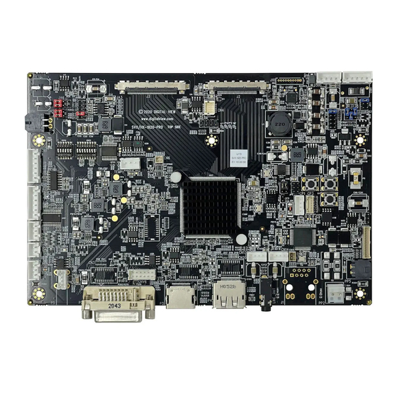
Model: SVX-1920-PRO
Part number : 41773002X-3 or up
INSTRUCTIONS
Page 1 of 47
Advertisement
Table of Contents

Related Manuals for digitalview SVX-1920-PRO


Summary of Contents for digitalview SVX-1920-PRO
-
Page 1: Table Of Contents
38. Appendix III – Mapping definition 41. Appendix IV – Auto Color Gain 42. Appendix V – DV remote control unit work for SVX-1920-PRO 43. Appendix VI – PIP mix table 44. Appendix VII – Light Sensor Function work for SVX-1920-PRO 45. - Page 2 Introduction Designed for LCD monitor and other flat panel display applications, the SVX-1920-PRO is a feature rich interface controller for : TFT (active matrix) LCD panels of 1920x1200, 1920x1080, 1920x480, 1680x1050, 1600x1200, 1600x900, 1440x900, 1366x768, 1280x1024, 1280x800, 1280x768 1024x768, 1024x600, 800x600, 800x480 and 640x480 resolutions.
- Page 3 SYSTEM DESIGN A typical LCD based display system utilizing this controller is likely to comprise the following: Specifications subject to change without notice © Digital View Ltd – Rev 1.20 (SVX-1920-PRO_manual.doc) Page 3 of 47...
- Page 4 ASSEMBLY NOTES This controller is designed for monitor and custom display projects using 1920x1200 or 1920x1080 or 1600x1200 or 1680x1050 or 1440x900 or 1366x768 or 1280 x 1024 or 1024 x 768 or 800x600 or 640x480 resolution TFT panels with a VGA, SVGA, WXGA, XGA, SXGA, UXGA or WUXGA signal input.
- Page 5 22. Audio Line out (Stereo) output from HDMI or Displayport : The CN14 port supports Stereo audio line out from the HDMI or Displayport audio source inputted. The audio output will follow the HDMI audio source. 23. Power Input: 12V/24VDC is required, this should be a regulated supply. The power rating is depending on the panel and inverter used.
- Page 6 10. Power supply & Controller: Plug the DC 12V/24V power in to the connector PP5 or PP2. You can consider to use DigitalView mating power cable P/N 426013800-3, 160mm for PP5 connection. 11. External panel power input : Plug power cable : P/N 426013700-3 for external panel power input (3.3 (max 7A) / 5V (max 7A) / 12V (max 5A) / 18V (max3.5))
- Page 7 LCD DISPLAY SYSTEM SETTINGS NOTE: By way of explanation the following refers to a set of sample buttons that may be obtained as an option. In addition to power on/off and connection for backlight brightness the controller provides an On Screen Display of certain functions which are controlled by 5 momentary type buttons (analog VR type) or 8 momentary type buttons (digital type): Controls Digital type...
- Page 8 OSD functions Picture Black Level Increase/decrease brightness level. Press – or + (- +) 0~100 [Default : 50] Increase/decrease contrast level. Contrast Press – or + (- + ) 0~100 [Default : 50] Sharpness Increase/decrease sharpness level. Press – or + (- + ) 0~100 [Default : 50] Increase/decrease hue level.
- Page 9 Factory Reset Press down on OSD keypad to factory reset Firmware Upgrade Are you sure to upgrade ? No / Yes. Information Model : SVX-1920-PRO Firmware version Main resolution Pip resolution # Function in VGA mode only Firmware V1.11.00.00 or up Specifications subject to change without notice ©...
- Page 10 CONNECTORS, PINOUTS & JUMPERS The various connectors are: Summary: Connectors Purpose Description Reserved for second RS-232 serial JST 6-way, B6B-XH-A or compatible (Matching type : XHP-6 or control compatible) (Matching cable with DB9 female connector P/N 426090200-3) (Matching cable with DB9 male connector P/N 426090400-3) Panel control signal (GPIO) Hirose 10-pin, DF20G-10DP-1V (Matching type : DF20A-10DS-1C)
- Page 11 CNV6 Alternate VGA input Hirose 12-pin, DF11-12DP-2DSA compatible (Matching type : DF11-12DS-2C) (Matching cable Modified P/N 426003300-3 by removing by disconnecting pin 10 and pin 12 connected to CNV6) Reserved for factory use Reserved Infra-red sensor connector JST 3-way, B3B-XH-A or compatible (Matching type : XHP-3) LED1 Dual color LED connector...
- Page 12 Table 1 : Panel voltage setting table : Input voltage via PP2/PP5 Panel Voltage Jumper on board 3.3V 3V3 closed 1-3 & 2-4 1-3 & 2-4 12VDC 5V closed 1-3 & 2-4 1-3 & 2-4 OPEN 1-3 & 2-4 5-7 & 6-8 CAUTION: Incorrect setting can damage panel &...
- Page 13 Input voltage via Input voltage via PP2 / PP5 Panel Voltage Jumper on board 3.3V OPEN 3-5 & 4-6 1-3 & 2-4 OPEN 3-5 & 4-6 1-3 & 2-4 3.3 / 5 / 12 / 12V / 24VDC OPEN 3-5 & 4-6 3-5 &...
- Page 14 JA3, JA5 & JA6 location on board : (Please pay attention to the jumper settings on JA3, JA5 & JA6 which are red in color) ! JA3, JA5 & JA6 Specifications subject to change without notice © Digital View Ltd – Rev 1.20 (SVX-1920-PRO_manual.doc) Page 14 of 47...
- Page 15 Table 2 : DIP Switch selection – SW3 Pos #1 Pos #2 Pos #3 Pos.#4 Description Panel resolution For WUXGA panels LG LM260WU1-SLB1/Samsung LTM220CS01 1920x1200 LG LM240WU2-SLA1 1920x1200 Sharp LQ445D3LZ19 1920x1080 Samsung LTA460H2-L02 1920x1080 Sharp LQ170M1LZ04 1920x1200 Samsung LTA700HH-LH1 (1 trial testing) 1920x1080 Samsung LTA700HH-LH1 (2...
- Page 16 Table 3 : DIP switch selection – SW4 Pos. # Function Description Reserved Panel pixel format OFF : Double Pixel ON : Single Pixel Panel selection ON : LVDS panel OFF : Reserved LVDS data mapping select If SW4 position 5 = OFF (8 bit) (Refer to Table 2) OFF : Mapping B ON : Mapping A...
- Page 17 CN1 – Slave RS-232 serial control: JST B6B-XH-A (Matching type : XHP-6) SYMBOL DESCRIPTION EXT_MSTR2_SCL Reserved EXT_MSTR2_SDA Reserved RS-232 Tx data Ground RS-232 Rx data CN4 – Panel connector: HIROSE DF20G-10DP-1V (Matching type : DF20A-10DS-1C) SYMBOL DESCRIPTION Reserved Reserved Reserved Reserved Reserved Reserved...
- Page 18 CN13 –Audio line in (Stereo) connector: JST B4B-PH-K compatible (Matching type : PHR-4) SYMBOL DESCRIPTION AUDIO LIN AUDIO LINE IN LEFT AUDIO RIN AUDIO LINE IN RIGHT CN14 –Audio line out (Stereo) connector: JST B4B-PH-K compatible (Matching type : PHR-4) SYMBOL DESCRIPTION AUDIO LOUT...
- Page 19 IR1 – Infra-Red sensor connector: JST B3B-XH-A (Matching type : XHP-3) SYMBOL DESCRIPTION Ground STDBY_Vcc Stand by voltage IR Data IR data J2 – LVDS output connector: JAE FI-RE41S-HF (Matching type : JAE FI-RE41HL) SYMBOL DESCRIPTION Ground LVDS_OUT2_B0- Negative differential LVDS data bit B0 LVDS_OUT2_B0+ Positive differential LVDS data bit B0 LVDS_OUT2_B1-...
- Page 20 Ground Ground LVDS_OUT1_A4+ Positive differential LVDS data bit A4 LVDS_OUT1_A4- Negative differential LVDS data bit A4 LVDS_OUT1_A3+ Positive differential LVDS data bit A3 LVDS_OUT1_A3- Negative differential LVDS data bit A3 Ground LVDS_OUT1_AC+ Positive LVDS clock for A channel LVDS_OUT1_AC- Negative LVDS clock for A channel Ground LVDS_OUT1_A2+ Positive differential LVDS data bit A2...
- Page 21 No connection P3 – HDMI 1.4 connector SYMBOL DESCRIPTION DATA2+ TMDS Data2+ DATA2S TMDS Data2 Shield DATA2- TMDS Data2– DATA1+ TMDS Data1+ DATA1S TMDS Data1 Shield DATA1- TMDS Data1– DATA0+ TMDS Data0+ DATA0S TMDS Data0 Shield DATA0- TMDS Data0– CLK+ TMDS Clock+ CLK@ TMDS Clock Shield...
- Page 22 PP4 – External panel power input DESCRIPTION External panel power Ground External panel power Ground PP5 – 12V/24VDC input power supply DESCRIPTION +12V / +24VDC Ground * All connectors used may use the compatible type. Specifications subject to change without notice ©...
-
Page 23: Controller Dimensions
Ready-made 3D Pro-E (SLDPRT) drawing files - Save time and effort for your system volumetric analysis design. Includes jpg file previews. Please go to download at https://digitalview.com/controllers/svx-1920-pro-lcd-controller.html The maximum thickness of the controller is 18.9mm with or without video add-on board (measured from bottom of PCB to top of components, including any underside components &... -
Page 24: Application Notes
APPLICATION NOTES USING THE CONTROLLER WITHOUT BUTTONS ATTACHED This is very straightforward: Firstly setup the controller/display system with the buttons. With controls attached and display system active make any • settings for colour, tint and image position as required then switch everything off. Remove the control switches, the 12-way (CNC1) cable. - Page 25 Design Guideline for making VR circuitry : Signal description / Notes : 1) R1 : 470ohm on board 2) RPOT is an external potentiometer (in-line dip style) that can be plugged directly into CNC1 pins 3,4,5. RPOT must be supplied / installed by user. 3) BVR_B : Voltage tapped from “top”...
-
Page 26: Troubleshooting
TROUBLESHOOTING General A general guide to troubleshooting a flat panel display system it is worth considering the system as separate elements, such Controller (jumpers, PC settings) Panel (controller, cabling, connection, panel, PC settings) Backlight (inverter, cabling, backlight tubes) Cabling Computer system (display settings, operating system) Through step by step cross checking with instruction manuals and a process of elimination to isolate the problem it is usually possible to clearly identify the problem area. -
Page 27: Specifications
SPECIFICATIONS Panel compatibility Compatible with 1920x1200, 1920x1080, 1920x480, 1680x1050, 1600x1200, 1600x900, 1440x900, 1366x768, 1280x1024, 1280x800, 1280x768 1024x768, 1024x600, 800x600, 800x480 and 640x480 resolutions of TFT LCD panels. A specified BIOS and some factory adjustment may be required for individual panel timings. No. - Page 28 APPENDIX I – SIGNAL SUPPORT MODE TABLE ARGB (P1) PORT : Mode Resolution Clk [MHz] Horizontal Vertical Sync Mode freq [KHz] freq [Hz] V_60 640x480 25.175 31.469 59.940 Digital Separate Sync 60Hz V_72 640x480 31.500 37.861 72.809 Digital Separate Sync 72Hz V_72 640x480...
- Page 29 UX_75 1600x1200 75.000 Sync On Green 60Hz WUX_60 1920x1080 172.8 67.5 Digital Separate Sync 60Hz WUX_60 1920x1080 172.8 67.5 Sync On Green 60Hz Remark : The controller has been designed to take a very wide range of input signals however to optimize the PC’s graphics performance we recommend choosing 60Hz vertical refresh rate.
- Page 30 Display port input port (DP 1.2) : Resolution Resolution Resolution 720p60 720p60 640x480 60Hz 720p59.94 720p59.94 640x480 72Hz 720p50 720p50 640x480 75Hz 720p30 720p30 720x480 60Hz 720p29.97 720p29.97 720x576 50Hz 720p25 720p25 800x600 56Hz 720p24 720p24 800x600 60Hz 720p23.976 720p23.976 800x600 72Hz 800x600 75Hz 1080i30...
-
Page 31: Appendix Ii - Rs-232 Control Protocols
The RS-232 program can be custom-made to fit for application or it can be used the serial control program, like Accessport, Telix or Serial Utility program developed by DigitalView. Please contact your local support for information. Specifications subject to change without notice ©... - Page 32 1. Commands to implement switch mount control buttons Function Command Description Remark Menu button 0xf7 Menu button pressed Button equivalent Select-down 0xfa Select-down button pressed Button equivalent button Select-up button 0xfb Select-up button pressed Button equivalent Right/+ button 0xfc Right/+ button pressed Button equivalent Left/- button 0xfd...
- Page 33 “r” | “R” | Reset nn = 0x00~ 0x64 (0~100%) “?” Query Default: 0x32 (50%) Frequency 0x8b, Set frequency = Graphic mode H active size (in nnnn | “+” | “-“ | Value/increment/decrement pixels) “?” Query Scaling Mode 0x8c, Set graphic image scaling mode Image expansion on/off.
- Page 34 “G” – Hue “H” – Brightness “I” – Auto Adjust "K" - PIP ON/OFF Hotkey 2 0xa0, “2”, Set Hotkey 2 = "1" - Volume value “2” – Black level “r” | “R” | Reset “3” – contrast (Default) “?” Query "4"...
- Page 35 “n” Minimum query Graphic horizontal 0xb7 Horizontal resolution (in pixels) in “nnn” = horizontal resolution resolution enquiry 3 digit hex number Graphic vertical 0xb8 Vertical resolution (in lines) in 3 “nnn” = vertical resolution resolution enquiry digit hex number Graphic horizontal 0xb9 Horizontal sync frequency (in “nnn”...
- Page 36 YY= Version Number ZZ= Customer Number Query PCBA 0xcb, “1” Read PCBA number “nnnnn” = PCBA number number SVX-1920-PRO= “41773” Query Revision 0xcb, “3” Read Revision Number “nn” = Revision number AA in Number firmware version no. “VV.YY.ZZ.AA” Reset to Factory...
- Page 37 Remark: “ “ “ “ *” ” ” ” - This command write to memory and therefore should not be set to write too frequency. We recommend no more than 1,000,000 times over a 3 years operating period. n = 1-byte ascii-coded hex number, e.g., parameter value of 0x1 is represented by “1” (0x31). mn or nn = 2-byte ascii-coded hex number, e.g., parameter value of 0x1e is represented by “1”, “e”...
-
Page 38: Appendix Iii - Mapping Definition
Appendix III – Mapping definition Definition of Mapping A : • Definition of Mapping B : • Specifications subject to change without notice © Digital View Ltd – Rev 1.20 (SVX-1920-PRO_manual.doc) Page 38 of 47... - Page 39 Definition of VESA : • Specifications subject to change without notice © Digital View Ltd – Rev 1.20 (SVX-1920-PRO_manual.doc) Page 39 of 47...
- Page 40 Definition of JEIDA : • Specifications subject to change without notice © Digital View Ltd – Rev 1.20 (SVX-1920-PRO_manual.doc) Page 40 of 47...
-
Page 41: Appendix Iv - Auto Color Gain
Appendix IV – Auto Color Gain The Auto Color Gain function is supported in the ARGB mode only and is designed to calibrate the controller to the incoming video signal. In order to calibrate correctly, the display must be displaying a FULL White image (see illustration below) when the function is used. The internal processor of the video controller chip will then execute a process to adjust the relative values of the RGB signals to achieve the best performance. -
Page 42: Appendix V - Dv Remote Control Unit Work For Svx-1920-Pro
Appendix V – DV remote control unit work for SVX-1920-PRO P/N 5590001xx-3 : DigitalView remote control unit (without DV logo silk screen printing) BUTTON FUNCTION POWER BUTTON Soft power ON/OFF button. 1. In OSD menu, pressing "SEL UP" button to move previous level of selection. -
Page 43: Appendix Vi - Pip Mix Table
Appendix VI – PIP mix table DVI-D HDMI Displayport PIP \ MAIN (P2/CNV6) (P2) (P3) (P4) VGA (P2/CNV6) DVI (P2) HDMI (P3) Displayport (P4) Specifications subject to change without notice © Digital View Ltd – Rev 1.20 (SVX-1920-PRO_manual.doc) Page 43 of 47... -
Page 44: Appendix Vii - Light Sensor Function Work For Svx-1920-Pro
Use of the light sensor board P/N 416021330-3 and light sensor cable P/N 426305900-3 connect to the SVX-1920-PRO via CN6 connector or use the light sensor cable P/N 426321940-3 as shown below : Digital View provides a user-friendly software program (TCP-IP Serial Utility V1.13 or later... - Page 45 TRADEMARKS The following are trademarks of Digital View Ltd: Digital View • SVX-1920-PRO • Specifications subject to change without notice © Digital View Ltd – Rev 1.20 (SVX-1920-PRO_manual.doc) Page 45 of 47...
-
Page 46: Contact Details
Digital View Inc. 18440 Technology Drive Building 130 Morgan Hill, California, 95037 Tel: (1) 408-782 7773 Fax: (1) 408-782 7883 Sales: ussales@digitalview.com EUROPE Digital View Ltd. The Lake House Knebworth Park Herts, SG3 6PY Tel: +44-(0)20-7631-2150 Fax: Fax: +44-(0)20-7631-2156 Sales: uksales@digitalview.com... -
Page 47: Revision History
426895100-3 for P5 -Remove LINE_OUT connector. Page 14 : - Update diagram to remove audio jack ( LINE_ OUT) connector on SVX-1920-PRO. Page 17 : - Add CN5 connector pin assignment table. Page 22 : - Update mechanical drawing to remove audio jack ( LINE_ OUT) connector and add CN5 connector on SVX-1920-PRO.
Need help?
Do you have a question about the SVX-1920-PRO and is the answer not in the manual?
Questions and answers