Table of Contents
Advertisement
Quick Links
Advertisement
Table of Contents

Related Manuals for MPP Solar HV V2 6048-T


Summary of Contents for MPP Solar HV V2 6048-T
- Page 1 User Manual HV V2 6048-T HYBRID INVERTER / CHARGER Version: 1.0...
-
Page 2: Table Of Contents
Table Of Contents ABOUT THIS MANUAL ............................. 1 Purpose ................................1 Scope ................................1 SAFETY INSTRUCTIONS ..........................1 INTRODUCTION ............................... 2 Product Overview ............................. 3 INSTALLATION ..............................4 Unpacking and Inspection..........................4 Preparation ..............................4 Mounting the Unit ............................. 4 Battery Connection ............................ -
Page 3: About This Manual
ABOUT THIS MANUAL Purpose This manual describes the assembly, installation, operation and troubleshooting of this unit. Please read this manual carefully before installations and operations. Keep this manual for future reference. Scope This manual provides safety and installation guidelines as well as information on tools and wiring. SAFETY INSTRUCTIONS WARNING: This chapter contains important safety and operating instructions. -
Page 4: Introduction
INTRODUCTION This hybrid PV inverter can provide power to connected loads by utilizing PV power, utility power and battery power. Hybrid inverter Distribution Box PV module Electric grids Load Battery Figure 1 Basic hybrid PV System Overview Depending on different power situations, this hybrid inverter is designed to generate continuous power from PV solar modules (solar panels), battery, and the utility. -
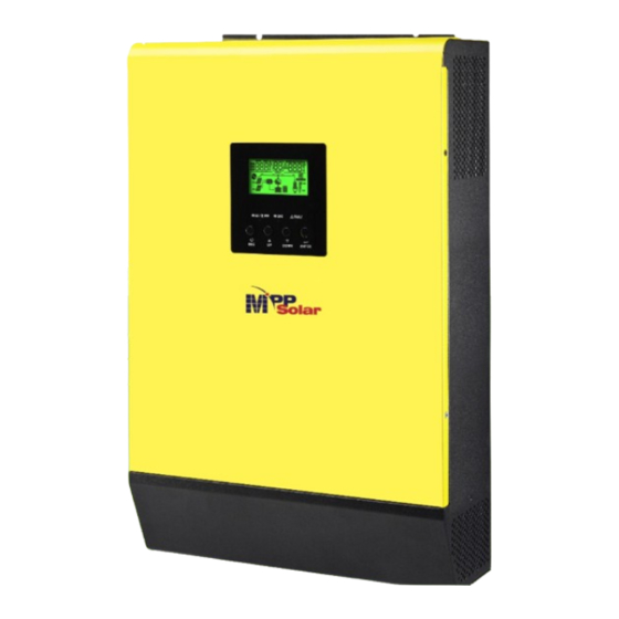
Page 5: Product Overview
Product Overview LCD display 9. PV connectors Status indicator 10. Battery connectors Charging indicator 11. Circuit breaker Fault indicator 12. Parallel communication ports Function buttons 13. Current sharing ports Power on/off switch 14. Dry contact AC output connectors (Load connection) 15. -
Page 6: Installation
INSTALLATION Unpacking and Inspection Before installation, please inspect the unit. Be sure that nothing inside the package is damaged. You should have received the following items inside of package: The unit x 1 User manual x 1 Communication cable x 2 ... -
Page 7: Battery Connection
Torque Amperage Capacity Cable Dimensions Value D (mm) L (mm) HV V2 6048-T 137A 200AH 1*2AWG 33.2 2~3 Nm Please follow below steps to implement battery connection: 1. Assemble battery ring terminal based on recommended battery cable and terminal size. -
Page 8: Ac Input/Output Connection
Suggested cable requirement for AC wires Model Gauge Torque Value HV V2 6048-T 10 AWG 1.2~ 1.6 Nm Please follow below steps to implement AC input/output connection: 1. Before making AC input/output connection, be sure to open DC protector or disconnector first. -
Page 9: Pv Connection
To reduce risk of injury, please use the proper recommended cable size as below. Model Typical Amperage Cable Size Torque HV V2 6048-T 10AWG 2.0~2.4Nm PV Module Selection: When selecting proper PV modules, please be sure to consider below parameters: 1. -
Page 10: Communication Connection
Recommended PV module Configuration PV Module Spec. Total solar input power Solar input Q'ty of modules (reference) 1500W 6 pieces in series 6 pcs - 250Wp - Vmp: 30.7Vdc 2000W 8 pieces in series 8 pcs - Imp: 8.15A - Voc: 37.4Vdc 2750W 11 pieces in series 11 pcs... -
Page 11: Operation
OPERATION Power ON/OFF Once the unit has been properly installed and the batteries are connected well, simply press On/Off switch (located on the bottom of the case) to turn on the unit. Operation and Display Panel The operation and display panel, shown in below chart, is on the front panel of the inverter. It includes three indicators, four function keys and a LCD display, indicating the operating status and input/output power information. -
Page 12: Lcd Display Icons
LCD Display Icons Icon Function Input source information Indicates the AC input Indicates the 1 PV panel input Indicates the 2 PV panel input Left digital display information Indicate input voltage, input frequency, battery voltage, PV1 voltage, PV2 voltage, charger current Middle digital display information Indicates the setting programs. -
Page 13: Lcd Setting
Mode operation information Indicates unit connects to the mains. Indicates unit connects to the 1 PV panel Indicates the solar charger is working Indicates the DC/AC inverter circuit is working. Mute operation Indicates unit alarm is disabled. LCD Setting After pressing and holding ENTER button for 3 seconds, the unit will enter setting mode. Press “UP” or “DOWN” button to select setting programs. - Page 14 220Vac 230V (Default) Output voltage 240Vac 50Hz (default) 60Hz Output frequency Charge first (default) Solar energy provides power to charge battery as first priority. Solar supply priority Load first Solar energy provides power to the loads as first priority. Overload bypass: Bypass disable Bypass enable When enabled, the unit will...
- Page 15 Solar and Utility Solar energy and utility will charge (default) battery at the same time. Charger source priority: Only Solar Solar energy will be the only charger To configure charger source source no matter utility is available or priority not. If this inverter/charger is working in Battery mode or Power saving mode, only solar energy can charge battery.
- Page 16 default setting: 40.8V Low DC cut off battery voltage setting If self-defined is selected in program 14, this program can be set up. Setting range is from 40.8V to 48.0V. Increment of each click is 0.1V. Low DC cut-off voltage will be fixed to setting value no matter what percentage of load is connected.
- Page 17 57.0V 58.0V Battery stop charging voltage when grid is available Return to default If selected, no matter how users display screen (default) switch display screen, it will automatically return to default display screen (Input voltage /output voltage) after no button is Auto return to default display screen pressed for 1 minute.
- Page 18 Reset Not reset(Default) Reset PV energy storage 00:00 (Default) Start charging time for AC charger The setting range of start charging time for AC charger is from 00:00 to 23:00, increment of each click is 1 hour. 00:00 (Default) Stop charging time for AC charger The setting range of stop charging time for AC charger is from 00:00 to 23:00, increment of each click is 1 hour.
- Page 19 Battery equalization enable Battery equalization disable (default) Battery equalization If “Flooded” or “User-Defined” is selected in program 05, this program can be set up. Default setting: 58.4V Battery equalization voltage Setting range is from 48.0V to 64.0V. Increment of each click is 0.1V.
- Page 20 Disable (Default) Setting discharge time on the Setting range is disable and then from 0 min to 990 min. 2nd output Increment of each click is 5 min. *If the battery discharge time exceeds the setting time in program 61 and the program 60 function is not triggered, the output will be turned off.
-
Page 21: Display Setting
Display Setting The LCD display information will be switched in turns by pressing “UP” or “DOWN” key. The selectable information is switched as below order: input voltage, input frequency, PV voltage, charging current, battery voltage, output voltage, output frequency, load percentage, load in Watt, load in VA, load in Watt, DC discharging current, main board firmware version and SCC firmware version. - Page 22 L2 output frequency L2 output frequency=50Hz Battery voltage and L1 output voltage Battery Voltage=48.0V, L1 output voltage=230V Battery voltage and total load percentage Battery Voltage=48.0V, total load percentage = 68% Battery voltage and total load in VA Battery Voltage=48.0V, total load in VA=1.08kVA...
- Page 23 Battery voltage and total load in Watt Battery Voltage=48.0V, total load in Watt=1.88kW PV1 voltage and PV1 charger power PV1 Voltage=360V, charging power=1.58kW Charger current and Charging current=30A, discharging current=0A DC discharging current PV energy generated today Today energy = 6.3kWh PV energy generated this month This month energy = 358kWh.
- Page 24 PV energy generated this year This year energy = 8.32MWh PV energy generated totally Total energy = 13.9MWh Real date Real date Nov 28, 2016. Real time Real time 13:20. Main board firmware version Version 00001.00...
-
Page 25: Operating Mode Description
Operating Mode Description Operating mode Behaviors LCD display Battery is charged by utility. Standby mode Battery is charged by PV energy. Note: *Standby mode: The inverter is not turned on yet but at Battery is charged by utility and PV energy. this time, the inverter can charge battery without AC No output power, solar... - Page 26 PV energy charges battery, utility and PV energy provide power to the load. Output power from Line mode utility. Charger PV energy charges battery, PV energy provides power available to the load and feeds remaining energy to the grid. PV energy and battery energy supply power to the load.
- Page 27 Warning Indicator Warning Code Warning Event Icon flashing Fan locked Over temperature Battery over charged Low battery Overload Inverter power derating PV is weak Battery is not connected...
- Page 28 Faults Reference Code Fault Code Fault Event Icon on Fan locked Over temperature Battery voltage is too high Battery voltage is too low Output short circuited Output voltage abnormal Over load time out Bus voltage is too high Bus soft start failed PV current over PV voltage over Charge current over...
- Page 29 Battery Equalization Equalization function is added into charge controller. It reverses the buildup of negative chemical effects like stratification, a condition where acid concentration is greater at the bottom of the battery than at the top. Equalization also helps to remove sulfate crystals that might have built up on the plates. If left unchecked, this condition, called sulfation, will reduce the overall capacity of the battery.
- Page 30 However, in Equalize stage, when battery equalized time is expired and battery voltage doesn’t rise to battery equalization voltage point, the charge controller will extend the battery equalized time until battery voltage achieves battery equalization voltage. If battery voltage is still lower than battery equalization voltage when battery equalized timeout setting is over, the charge controller will stop equalization and return to float stage.
-
Page 31: Specifications
SPECIFICATIONS MODEL HV V2 6048-T RATED OUPUT POWER 6000W PV INPUT (DC) Max. PV Power 7000W Max. PV Array Open Circuit Voltage 500 VDC MPPT Range @ Operating Voltage 120 VDC~430 VDC Number of MPP Tracker GRID-TIE OPERATION GRID OUTPUT (AC) -
Page 32: Trouble Shooting
TROUBLE SHOOTING Problem LCD/LED/Buzzer Explanation / Possible cause What to do Unit shuts down LCD/LEDs and buzzer automatically will be active for 3 The battery voltage is too low 1. Re-charge battery. during startup seconds and then (<1.91V/Cell) 2. Replace battery. process. -
Page 33: Appendix I: Parallel Function
Appendix I: Parallel function 1. Introduction This inverter can be used in parallel with two different operation modes. 1. Parallel operation in single phase with up to 9 units. The supported maximum output power is 54KW/54KVA. 2. Maximum nine units work together to support three-phase equipment. Seven units support one phase maximum. - Page 34 Step 3: Remove two screws as below chart and remove 2-pin and 14-pin cables. Take out the board under the communication board. Step 4: Remove two screws as below chart to take out cover of parallel communication. Step 5: Install new parallel board with 2 screws tightly. Step 6: Re-connect 2-pin and 14-pin to original position.
- Page 35 Model Wire Size value D (mm) L (mm) HV V2 6048-T 1*2AWG 33.2 2~ 3 Nm WARNING: Be sure the length of all battery cables is the same. Otherwise, there will be voltage difference between inverter and battery to cause parallel inverters...
- Page 36 Recommended AC input and output cable size for each inverter: Model AWG no. Torque HV V2 6048-T 10 AWG 1.2~1.6Nm You need to connect the cables of each inverter together. Take the battery cables for example: You need to use a connector or bus-bar as a joint to connect the battery cables together, and then connect to the battery terminal.
- Page 37 5-1. Parallel Operation in Single phase Two inverters in parallel: Power Connection Load Communication Connection Three inverters in parallel: Power Connection Load...
- Page 38 Communication Connection Four inverters in parallel: Power Connection Load Communication Connection Five inverters in parallel: Power Connection Load...
- Page 39 Communication Connection Six inverters in parallel: Power Connection Load Communication Connection Seven to nine inverters in parallel: Power Connection Load Communication Connection Seven inverters in parallel ❸ ❹ ❺ ❼ ❶ ❷ ❻...
- Page 40 Eight inverters in parallel ❶ ❷ ❸ ❹ ❺ ❻ ❼ ❽ Nine inverters in parallel ❸ ❹ ❺ ❼ ❽ ❾ ❶ ❷ ❻ 5-2. Support 3-phase equipment Three inverters in each phase: Power Connection Load Communication Connection ①...
- Page 41 Communication Connection ❶ ❷ ❸ ❹ ❺ ❻ ❼ ❽ Three inverters in one phase, two inverters in second phase and two inverters for the third phase: Power Connection Load Communication Connection ❸ ❹ ❺ ❼ ❶ ❷ ❻ Two inverters in each phase: Power Connection Load Communication Connection...
- Page 42 Four inverters in one phase and one inverter for the other two phases: Power Connection Load Communication Connection Three inverters in one phase, two inverters in second phase and one inverter for the third phase: Power Connection Load Communication Connection...
- Page 43 Three inverters in one phase and only one inverter for the remaining two phases: Power Connection Load Communication Connection Two inverters in two phases and only one inverter for the remaining phase: Power Connection Load Communication Connection...
- Page 44 Two inverters in one phase and only one inverter for the remaining phases: Power Connection Load Communication Connection One inverter in each phase: Power Connection Load Communication Connection WARNING: Do not connect the current sharing cable between the inverters which are in different phases. Otherwise, it may damage the inverters.
- Page 45 7. LCD Setting and Display Setting Program: Program Description Selectable option Single: When the units are used in parallel with single phase, please select “PAL” in program It is required to have at least 3 inverters or Parallel: maximum 6 inverters to support three-phase equipment.
- Page 46 8. Commissioning Parallel in single phase Step 1: Check the following requirements before commissioning: Correct wire connection Ensure all breakers in Line wires of load side are open and each Neutral wires of each unit are connected together. Step 2: Turn on each unit and set “PAL”...
- Page 47 Step 5: If there is no more fault alarm, the system to support 3-phase equipment is completely installed. Step 6: Please switch on all breakers of Line wires in load side. This system will start to provide power to the load.
Need help?
Do you have a question about the HV V2 6048-T and is the answer not in the manual?
Questions and answers