
Subscribe to Our Youtube Channel
Related Manuals for RF-Star RF-WM-11AFB1


Summary of Contents for RF-Star RF-WM-11AFB1
- Page 1 RF-WM-11AFB1 Ultra-Low-Power 2.4 GHz Wi-Fi Module Version 1.0 Shenzhen RF-star Technology Co., Ltd. Jan. 19 , 2020...
-
Page 2: Wi-Fi Module List
3. All modules with PCB / Chip antenna and IPEX connector are dispatched with PCB / Chip antenna only by default. If IPEX connector is needed, pls check with me before quotation. Shenzhen RF-star Technology Co., Ltd. Page 1 of 23... -
Page 3: Device Overview
1 Device Overview 1.1 Description RF-WM-11AFB1 is a PCB module based on Realtek Wi-Fi SoC RTL8711AF of Cortex -M3 core at 83 MHz. This module has on-chip 512 KB RAM and 1 MB flash, a pin-out of peripherals of SDIO, SPI, UART, I C, I S, and GPIOs. -
Page 4: Applications
1.4 Functional Block Diagram 40.0 MHz NFC Out Antenna Switch IPEX Connector Matching GPIOs RTL8711AF Antenna Matching Antenna Power Supply Reset 3.0 V ~ 3.6 V Figure 1. Functional Block Diagram of RF-WM-11AFB1 Shenzhen RF-star Technology Co., Ltd. Page 3 of 23... -
Page 5: Part Number Conventions
RF-WM-10AFB1 www.szrfstar.com V1.0 - Jan., 2020 1.5 Part Number Conventions The part numbers are of the form of RF-WM-11AFB1 where the fields are defined as follows: 11AF Company Name Module Version The First Version RF-Star Wireless Type Chipset Model Wi-Fi Module Realtek RTL8711AF Figure 2. -
Page 6: Table Of Contents
4.6 Basic Operation of Hardware Design ...................... 16 4.7 Trouble Shooting .............................. 18 4.7.1 Unsatisfactory Transmission Distance ..................18 4.7.2 Vulnerable Module ..........................18 4.7.3 High Bit Error Rate ..........................18 Shenzhen RF-star Technology Co., Ltd. Page 5 of 23... -
Page 7: Table Of Figures
Figure 3. Pin Diagram of RF-WM-11AFB1 ...................... 7 Figure 4. Photos of RF-WM-11AFB1 ....................... 13 Figure 5. Recommended PCB Footprint of RF-WM-11AFB1 (mm) ............. 13 Figure 6. Specification of Antenna Seat ......................14 Figure 7. Specification of IPEX Wire ........................ 14 Figure 8. -
Page 8: Module Configuration And Functions
Type of Antenna PCB antenna / IPEX connector -20 ℃ ~ +85 ℃ Operating Temperature -40 ℃ ~ +125 ℃ Storage Temperature 2.2 Module Pin Diagram Figure 3. Pin Diagram of RF-WM-11AFB1 Shenzhen RF-star Technology Co., Ltd. Page 7 of 23... -
Page 9: Pin Functions
RF-WM-10AFB1 www.szrfstar.com V1.0 - Jan., 2020 2.3 Pin Functions Table 2. Pin Functions of RF-WM-11AFB1 Name Description RFOUT RF signal output pin Ground Ground 3.3 V power supply GPIO_E4 GPIO pin, the MUX function can be referred to pin multiplexing table. - Page 10 GPIO pin, the MUX function can be referred to pin multiplexing table. GPIO_B0 GPIO pin, the MUX function can be referred to pin multiplexing table. NFCIP NFC differential signal input NFCIN NFC differential signal input Ground Shenzhen RF-star Technology Co., Ltd. Page 9 of 23...
-
Page 11: Pin Multiplexing
RF-WM-10AFB1 www.szrfstar.com V1.0 - Jan., 2020 2.4 Pin Multiplexing Table 3. Pin Multiplexing of RF-WM-11AFB1 WKDT GPIO INT Pin name JTAG SDIO UART Group I2C Group SPI Group I2S Group PCM Group Wl_LED Default State SCHMT GPIO_A0 SD_D2 UART2_IN SPI1_MISO... -
Page 12: Specifications
-63 dBm 3.3.2 Transmission Distance The transmission distance test was conducted in the outdoor open area, and two RF-WM-11AFB1 modules were marked as A0 and B0 respectively. And the simultaneous bidirectional communication test was conducted under the modules with external rod antenna and PCB antenna. The test results are as follows: Shenzhen RF-star Technology Co., Ltd. - Page 13 Packet Packet Packet Packet Loss Rate Loss Rate A0→B0 1000 1000 1000 1000 Antenna A0B0 1000 1000 1000 1000 A0→B0 1000 1000 1000 1000 External Antenna A0B0 1000 1000 1000 1000 Shenzhen RF-star Technology Co., Ltd. Page 12 of 23...
-
Page 14: Application, Implementation, And Layout
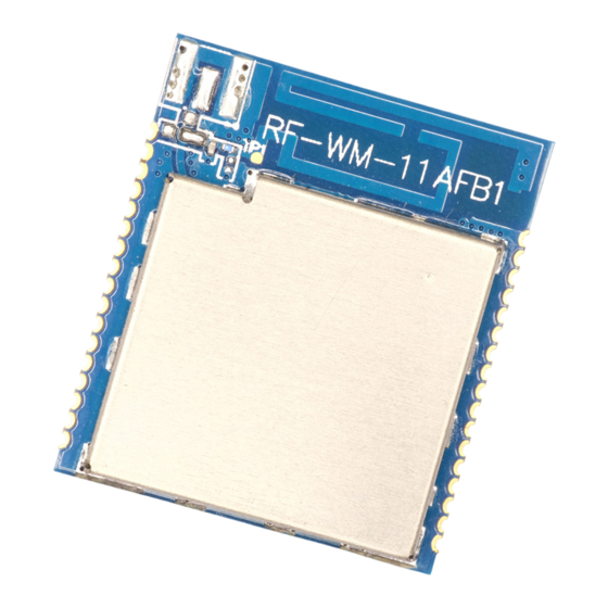
RF-WM-10AFB1 www.szrfstar.com Ver1.0 - Jan., 2020 4 Application, Implementation, and Layout 4.1 Module Photos Figure 4. Photos of RF-WM-11AFB1 4.2 Recommended PCB Footprint Figure 5. Recommended PCB Footprint of RF-WM-11AFB1 (mm) Shenzhen RF-star Technology Co., Ltd. Page 13 of 23... -
Page 15: Antenna
Ver1.0 - Jan., 2020 4.3 Antenna RF-WM-11AFB1 module is integrated the IPEX version 1 antenna seat, the specification of antenna seat is as follow: Figure 6. Specification of Antenna Seat The specification of IPEX wire end is as follow: Figure 7. -
Page 16: Schematic Diagram
RF-WM-10AFB1 www.szrfstar.com Ver1.0 - Jan., 2020 4.4 Schematic Diagram Figure 8. Schematic Diagram of RF-WM-11AFB1 Shenzhen RF-star Technology Co., Ltd. Page 15 of 23... -
Page 17: Download And Debug Interface
Figure 9. Download and Debug Interface of RF-WM-11AFB1 Regarding the download and debugging methods of the module, please cooperate with the RF-DK-871xB1 development board provided by RF-star. For related information, please refer to the "RF-DK-871xB1 development board user manual". 4.6 Basic Operation of Hardware Design 1. -
Page 18: Figure 10. Recommendation Of Antenna Layout
(3) It is the best to hollow out the antenna position in the following figure so as to ensure that S11 of the module is minimally affected. (4) The impedance of external IPEX interface is 50 Ω. Figure 10. Recommendation of Antenna Layout Note: The hollow-out position is based on the antenna used. Shenzhen RF-star Technology Co., Ltd. Page 17 of 23... -
Page 19: Trouble Shooting
3. If the extension wire or feeder wire is of poor quality or too long, the bit error rate will be high. 4.8 Electrostatics Discharge Warnings The module will be damaged for the discharge of static. RF-star suggest that all modules should follow the 3 precautions below: 1. -
Page 20: Soldering And Reflow Condition
Max. 6 ℃/s Average Descend Rate (T to T Time from 25 ℃ to Peak Temperature (t Max. 6 minutes Max. 8 minutes 20±10 s 20±10 s Time of Soldering Zone (t Shenzhen RF-star Technology Co., Ltd. Page 19 of 23... -
Page 21: Optional Packaging
RF-WM-10AFB1 www.szrfstar.com Ver1.0 - Jan., 2020 Figure 11. Recommended Reflow for Lead Free Solder 4.10 Optional Packaging Figure 12. Optional Packaging Mode Note: Default tray packaging. Shenzhen RF-star Technology Co., Ltd. Page 20 of 23... -
Page 22: Certificates
RF-WM-10AFB1 www.szrfstar.com Ver1.0 - Jan., 2020 5 Certificates 5.1 RoHS Figure 13. RoHS Certificate Shenzhen RF-star Technology Co., Ltd. Page 21 of 23... -
Page 23: Revision History
1. The document will be optimized and updated from time to time. Before using this document, please make sure it is the latest version. 2. To obtain the latest document, please download it from the official website: www.szrfstar.com. Shenzhen RF-star Technology Co., Ltd. Page 22 of 23... -
Page 24: Contact Us
RF-WM-10AFB1 www.szrfstar.com Ver1.0 - Jan., 2020 7 Contact Us SHENZHEN RF-STAR TECHNOLOGY CO., LTD. Shenzhen HQ: Add.: Room 601, Block C, Skyworth Building, High-tech Park, Nanshan District, Shenzhen, Guangdong, China Tel.: 86-755-8632 9687 Chengdu Branch: Add.: No. B3-03, Building No.1, Incubation Park, High-Tech District, Chengdu, Sichuan, China, 610000 Tel.: 86-28-6577 5970...
Need help?
Do you have a question about the RF-WM-11AFB1 and is the answer not in the manual?
Questions and answers