
Subscribe to Our Youtube Channel
Related Manuals for RF-Star RF-SM-1077B2


Summary of Contents for RF-Star RF-SM-1077B2
- Page 1 RF-SM-1077B2 Ultra-Low-Power 433 MHz & 470 MHz Wireless Module Version 2.1 Shenzhen RF-star Technology Co., Ltd. Apr. 09 , 2020...
-
Page 2: Ti Cc131X Sub-1 Ghz Module List
1. The communication distance is the longest distance obtained by testing the module's maximum transmission power in an open and interference-free environment in sunny weather. 2. Click the picture to buy modules. Shenzhen RF-star Technology Co., Ltd. Page 1 of 30... -
Page 3: Device Overview
RF-SM-1077B2 www.szrfstar.com V2.1- Apr., 2020 1 Device Overview 1.1 Description RF-SM-1077B2 Sub-1 GHz module is based on TI CC1310, which combines a flexible, very low-power RF transceiver with a powerful 48 MHz ARM ® Cortex ® -M3 microcontroller supporting multiple physical layers and RF standards and a dedicated radio controller Cortex ®... -
Page 4: Applications
1.4 Functional Block Diagram 24.0 MHz 32.768 kHz CC1310 GPIOs Balun Antenna IPEX Band Pass Matching Interface Filter Power Supply Reset 1.8 V ~ 3.8 V Figure 1. Functional Block Diagram of RF-SM-1077B2 Shenzhen RF-star Technology Co., Ltd. Page 3 of 30... -
Page 5: Working Mode
V2.1- Apr., 2020 1.5 Working Mode Figure 2. Working Mode of RF-SM-1077B2 1.6 Part Number Conventions The part numbers are of the form of RF-SM-1077B2 where the fields are defined as follows: 1077 RF-STAR Module Version The Second Version... -
Page 6: Table Of Contents
5.1 AT Command Format Description ......................16 5.2 AT Commands ..............................17 5.2.1 Start / Exit AT Command Mode ..................... 17 5.2.2 Parameter Query / Configuration ....................17 5.2.3 RF Power Query / Configuration ....................17 Shenzhen RF-star Technology Co., Ltd. Page 5 of 30... -
Page 7: Table Of Figures
8 Revision History ................................29 9 Contact Us ..................................30 Table of Figures Figure 1. Functional Block Diagram of RF-SM-1077B2 ................3 Figure 2. Working Mode of RF-SM-1077B2....................4 Figure 3. Part Number Conventions of RF-SM-1077B2 ................4 Figure 4. Pin Diagram of RF-SM-1077B2 ......................9 Shenzhen RF-star Technology Co., Ltd. -
Page 8: Table Of Tables
V2.1- Apr., 2020 Figure 5. Photos of RF-SM-1077B2 ......................... 22 Figure 6. Recommended PCB Footprint of RF-SM-1077B2 (mm) ............22 Figure 7. Specification of Antenna Seat ......................23 Figure 8. Specification of IPEX Wire ........................ 23 Figure 9. Schematic Diagram of RF-SM-1077B2 ..................24 Figure 10. -
Page 9: Module Configuration And Functions
RF-SM-1077B2 www.szrfstar.com V2.1- Apr., 2020 2 Module Configuration and Functions 2.1 Module Parameters Table 1. Parameters of RF-SM-1077B2 Chipset CC1310F128RGZ Supply Power Voltage 1.8 V ~ 3.8 V, recommended to 3.3 V Frequency 433 MHz, 470 MHz Maximum Transmit Power +15.0 dBm... -
Page 10: Module Pin Diagram
RF-SM-1077B2 www.szrfstar.com V2.1- Apr., 2020 2.2 Module Pin Diagram Figure 4. Pin Diagram of RF-SM-1077B2 2.3 Pin Functions Table 2. Pin Functions of RF-SM-1077B2 Name Chip Pin Pin Type Description DIO_1 Digital I/O GPIO, Sensor Controller DIO_2 Digital I/O RX (GPIO, Sensor Controller) - Page 11 DIO_29 Digital or analog I/O GPIO, Sensor Controller, analog DIO_30 Digital or analog I/O GPIO, Sensor Controller, analog 1.8 V ~ 3.6 V, recommended to 3.3 V External antenna pin ground Shenzhen RF-star Technology Co., Ltd. Page 10 of 30...
-
Page 12: Specifications
Functional operation does not guarantee performance beyond the limits of the conditional parameter values in the table below. Long-term work beyond this limit will affect the reliability of the module more or less. Table 3. Recommended Operating Conditions of RF-SM-1077B2 Items Min. - Page 13 Peripheral Current Consumption (Adds to core current I for each peripheral unit activated) (1) (2) (3) core Peripheral power Delta current with domain enabled µA domain peri Serial power Delta current with domain enabled µA domain Shenzhen RF-star Technology Co., Ltd. Page 12 of 30...
-
Page 14: Power Consumption Test
(2) I is not supported in standby or shutdown modes. peri (3) Measured at 3.0 V. 3.3.2 Power Consumption Test Table 6. Power Consumption of RF-SM-1077B2 Min. Current Max. Current Average Current Samples Mode 1.29 mA 1.32 mA... -
Page 15: Functions
RTC. Sensor Controller controls 7 digital I/Os (DIO1 ~ DIO7), 8 digital/simulation I/Os (DIO23 ~ DIO30), and these I/Os can be configured as SPI, I C, ADC etc. Shenzhen RF-star Technology Co., Ltd. Page 14 of 30... - Page 16 AD acquisition, and collect data once every second by default. Users can control the enable and disable of AD voltage collection through AT commands (please refer to “AT command” chapter for details). Shenzhen RF-star Technology Co., Ltd. Page 15 of 30...
-
Page 17: At Command
Parameter configuration: Different configuration parameters have different range of values, please refer to t“AT Command” for details. Command end character: AT Command terminator is used to indicate that the command ends, which is fixed as carriage return linefeed “↲”(\r\n). Shenzhen RF-star Technology Co., Ltd. Page 16 of 30... -
Page 18: At Commands
If the command format is incorrect, the serial port will return "ERROR↲". "AT#RF-Pxx↲": Configure RF power. Enter the command into serial port. When the serial port prints "OK↲", which means successful operation. In the Shenzhen RF-star Technology Co., Ltd. Page 17 of 30... -
Page 19: Channel Query / Configuration
Enter the command into serial port. When the serial port prints "OK↲", which means successful operation. In the command, “-C” means the RF channel. The parameter of RF-SM-1077B2 supports any value from 0 to 6. If the command format is incorrect, the serial port will return "ERROR↲". -
Page 20: Software / Hardware Version Query
"OK" indicates successful operation. Otherwise, the operation failed. • "AT#VER↲": Query Module software and hardware version. "OK" indicates successful operation and the serial port will return AT#VER software and hardware version, such as: AT#VER-Sm1.0.0-D1077B1. Otherwise, the operation failed. Shenzhen RF-star Technology Co., Ltd. Page 19 of 30... - Page 21 • "AT#ADC-E0↲": Disable data collection of ADC channel 0,1. collection "OK" indicates successful operation and shuts down data collection of channel ADC channel 0,1. • "AT#CHN↲": Query RF channel. AT#CHN -C: RF channel setup Shenzhen RF-star Technology Co., Ltd. Page 20 of 30...
- Page 22 • "AT#CHN-C1↲": Configure RF channel. Set RF channel value as 1, "OK" indicates successful operation and the parameter will be effective after restart. Note: AT Command with “•” is the completed one. Shenzhen RF-star Technology Co., Ltd. Page 21 of 30...
-
Page 23: Application, Implementation, And Layout
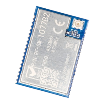
RF-SM-1077B2 www.szrfstar.com V2.1- Apr., 2020 6 Application, Implementation, and Layout 6.1 Module Photos Figure 5. Photos of RF-SM-1077B2 6.2 Recommended PCB Footprint Figure 6. Recommended PCB Footprint of RF-SM-1077B2 (mm) Shenzhen RF-star Technology Co., Ltd. Page 22 of 30... -
Page 24: Antenna
V2.1- Apr., 2020 6.3 Antenna RF-SM-1077B2 module is integrated the IPEX version 1 antenna seat, the specification of antenna seat is as follow: Figure 7. Specification of Antenna Seat The specification of IPEX wire end is as follow: Figure 8. Specification of IPEX Wire Shenzhen RF-star Technology Co., Ltd. -
Page 25: Schematic Diagram
V2.1- Apr., 2020 6.4 Schematic Diagram Figure 9. Schematic Diagram of RF-SM-1077B2 6.5 Basic Operation of Hardware Design 1. It is recommended to offer the module with a DC stabilized power supply, a tiny power supply ripple coefficient and the reliable ground. -
Page 26: Trouble Shooting
Please ensure the stable power supply and no frequently fluctuated voltage. 2. Please ensure the anti-static installation and the electrostatic sensitivity of high-frequency devices. 3. Due to some humidity sensitive components, please ensure the suitable humidity during installation and application. Shenzhen RF-star Technology Co., Ltd. Page 25 of 30... -
Page 27: High Bit Error Rate
3. If the extension wire or feeder wire is of poor quality or too long, the bit error rate will be high. 6.7 Electrostatics Discharge Warnings The module will be damaged for the discharge of static. RF-star suggest that all modules should follow the 3 precautions below: 1. -
Page 28: Optional Packaging
RF-SM-1077B2 www.szrfstar.com V2.1- Apr., 2020 Figure 10. Recommended Reflow for Lead Free Solder 6.9 Optional Packaging Figure 11. Optional Packaging Mode Note: Default tray packaging. Shenzhen RF-star Technology Co., Ltd. Page 27 of 30... -
Page 29: Certification
RF-SM-1077B2 www.szrfstar.com V2.1- Apr., 2020 7 Certification 7.1 Reach Reach Certificate No.: C181213010001 Figure 12. SRRC Certificate 7.2 RoHS Reach Certificate No.: C181213010002 Figure 13. RoHS Certificate Shenzhen RF-star Technology Co., Ltd. Page 28 of 30... -
Page 30: Revision History
2018.03.12 V2.0 Add commands. Levi 2018.01.24 V2.1 Add inquiry MAC address function. Levi 2018.08.02 V2.1 Update company address. Aroo Wang 2020.04.09 V2.1 Add TI CC131X Sub-1 GHz module list. Sunny Li Shenzhen RF-star Technology Co., Ltd. Page 29 of 30... -
Page 31: Contact Us
RF-SM-1077B2 www.szrfstar.com V2.1- Apr., 2020 9 Contact Us SHENZHEN RF-STAR TECHNOLOGY CO., LTD. Shenzhen HQ: Add.: Room 601, Block C, Skyworth Building, High-tech Park, Nanshan District, Shenzhen, Guangdong, China Tel.: 86-755-3695 3756 Chengdu Branch: Add.: No. B4-12, Building No.1, No. 1480 Tianfu Road North Section (Incubation Park), High-Tech Zone, Chengdu, China (Sichuan) Free Trade Zone, 610000 Tel.: 86-28-6577 5970...
Need help?
Do you have a question about the RF-SM-1077B2 and is the answer not in the manual?
Questions and answers