
Related Manuals for RF-Star RF-BM-ND06


Summary of Contents for RF-Star RF-BM-ND06
- Page 1 RF-BM-ND06 Bluetooth 5.0 Module Version 1.0 Shenzhen RF-star Technology Co., Ltd. Dec. 06, 2018...
-
Page 2: Device Overview
It supports BLE stack v5.0 and can be preprogrammed with a serial interface communication protocol for simple programming. 1.27-mm pitch stamp stick package for easy assembling and cost-effective PCB design. All pins of RF-BM-ND06 are pulled out. 1.2 Key Features •... -
Page 3: Applications
• Access Control • Remote controls 1.4 Functional Block Diagram Confidential 1.5 Part Number Conventions The part numbers are of the form of RF-BM-ND06 where the fields are defined as follows: RF-STAR Module Version Version Number Company Name Bluetooth Module... - Page 4 This exterior label can use wording such as the following: “Contains Transmitter Module FCC ID: 2ABN2-RF-BM-ND06 Or Contains FCC ID: 2ABN2-RF-BM-ND06” When the module is installed inside another device, the user manual of the host must contain below warning statements;...
- Page 5 15.207 ,15B Class B requirement, Only if the test result comply with FCC part 15C : 15.247 and 15.209 & 15.207 ,15B Class B requirement,then the host can be sold legally. Shenzhen RF-star Technology Co., Ltd. Page 4 of 21...
-
Page 6: Table Of Contents
4.7 Electrostatics Discharge Warnings ..................18 4.8 Soldering and Reflow Condition ....................18 4.9 Optional Packaging ........................19 5 Certification ............................19 5.1 RoHS ............................19 6 Revision History ............................ 20 Shenzhen RF-star Technology Co., Ltd. Page 5 of 21... -
Page 7: Table Of Figures
- Dec., 2018 7 Contact Us ............................. 20 Table of Figures Figure 1. Functional Block Diagram of RF-BM-ND06 ..............2 Figure 2. Part Number Conventions of RF-BM-ND06 ..............2 Figure 3. Pin Diagram of RF-BM-ND06 ................... 8 Figure 4. Photos of RF-BM-ND06 ....................14 Figure 5. -
Page 8: Module Configuration And Functions
RF-BM-ND06 www.szrfstar.comVer1.0 - Dec., 2018 2 Module Configuration and Functions 2.1 Module Parameters Table 1. Parameters of RF-BM-ND06 Chipset nRF52840QIAA-R Supply Power Voltage 1.8 V ~ 5.5 V, recommended to 3.3 V Frequency 2402 MHz ~ 2480 MHz Maximum Transmit Power -20.0 dBm ~ +8.0 dBm... -
Page 9: Module Pin Diagram
RF-BM-ND06 www.szrfstar.comVer1.0 - Dec., 2018 2.2 Module Pin Diagram Figure 2. Pin Diagram of RF-BM-ND06 2.3 Pin Functions Table 2. Pin Functions of RF-BM-ND06 Name Chip Pin Pin Type Description P0.12 SIO_12 Power 1.7V ~ 3.6V 1.7V ~ 3.6V VDD_HV Power 2.5V ~ 5.5V... - Page 10 FTDI USB_DTR via jumper on nAutoRUN nAutoRUN P1.03 J12pin1-2. GPIO_1.04 P1.04 GPIO_1.05 P1.05 GPIO_1.06 P1.06 RF-interface RF_OUT GPIO_1.07 P1.07 GPIO_1.10 P1.10 GPIO_1.11 P1.11 GPIO_1.12 SPI_CS P1.12 GPIO_1.13 P1.13 GPIO_1.14 P1.14 GPIO_1.15 P1.15 Shenzhen RF-star Technology Co., Ltd. Page 9 of 21...
-
Page 11: Specifications
Functional operation does not guarantee performance beyond the limits of the conditional parameter values in the table below. Long-term work beyond this limit will affect the reliability of the module more or less. Table 3. Recommended Operating Conditions of RF-BM-ND06 Items Condition Min. -
Page 12: Handling Ratings
(1) The operating temperature is limited to the operating temperature range of crystal. The temperature range can be wider by changing the crystal. (2) To ensure the RF performance, the ripple wave on the source must be less than ±200 mV. 3.2 Handling Ratings Table 4. Handling Ratings of RF-BM-ND06 Items Condition Min. - Page 13 BLEmode, Clock = HFXO, Regulator = DC/DC Radio transmitting @ 0 dBm output power, 1 Mbps BLE RADIO_TX1 mode, Clock = HFXO, Regulator = DC/DC Radio transmitting @ -40 dBm output power, 1 Mbps BLE 3.83 RADIO_TX2 Shenzhen RF-star Technology Co., Ltd. Page 12 of 21...
- Page 14 CPU running CoreMark from flash, Radio transmitting @ 0 dBm output power, 1 Mbps Bluetooth® low energy (BLE) mode, Clock = HFXO, Regulator = DC/DC CPU running CoreMark from flash, Radio receiving @ 1 Shenzhen RF-star Technology Co., Ltd. Page 13 of 21...
-
Page 15: Application, Implementation, And Layout
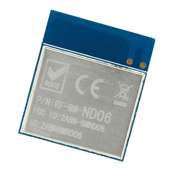
Mbps BLE mode, Clock = HFXO, Regulator = DC/DC, 5 V 12.7 supply on VDDH, REG0 output = 3.3 V 4 Application, Implementation, and Layout 4.1 Module Photos Figure 3. Photos of RF-BM-ND06 Shenzhen RF-star Technology Co., Ltd. Page 14 of 21... -
Page 16: Recommended Pcb Footprint
RF-BM-ND06 www.szrfstar.comVer1.0 - Dec., 2018 4.2 Recommended PCB Footprint Figure 4. Top View of RF-BM-ND06 (mm) 4.3 Schematic Diagram Confidential Figure 5. Schematic Diagram of RF-BM-ND06 4.5 Basic Operation of Hardware Design 1. It is recommended to offerthe module with a DC stabilized power supply, a tiny power supply ripple coefficient and the reliable ground. - Page 17 (2) Make sure that there is no signal line or copper foil in each layer below the antenna. (3) It is the best to hollow out the antenna position in the following figure so as to ensure that S11 of the module is minimally affected. Shenzhen RF-star Technology Co., Ltd. Page 16 of 21...
-
Page 18: Trouble Shooting
3. The signal attenuation will be very obvious, if there is a metal near the antenna or themodule is placed inside of the metal shell. 4. The incorrect power register set or the high data ratein an open air may shorten the communication distance.The higher the data rate, the closer the distance. Shenzhen RF-star Technology Co., Ltd. Page 17 of 21... -
Page 19: Vulnerable Module
3. If the extension wire or feeder wire is of poor quality or too long, the bit error rate will be high. 4.7Electrostatics Discharge Warnings The module will be damaged for the discharge of static. RF-star suggest that all modules should follow the 3 precautions below: 1. -
Page 20: Optional Packaging
- Dec., 2018 Figure 7. Recommended Reflow for Lead Free Solder 4.9 Optional Packaging Figure 8. Optional Packaging Mode Note: Default tray packaging. 5 Certification 5.1 RoHS RoHS Report No.: BLA-C-201811-A05-01 Shenzhen RF-star Technology Co., Ltd. Page 19 of 21... -
Page 21: Revision History
2018.12.06 V1.0 Update module Parameter. Aroo Wang 7 Contact Us SHENZHEN RF-STAR TECHNOLOGY CO., LTD. Shenzhen HQ: Add.: Room 601, Block C, Skyworth Building, High-tech Park, Nanshan District, Shenzhen, Guangdong, China Tel.: 86-755-8632 9687 Chengdu Branch: Add.: No. B4-12, Building No.1, No. 1480 Tianfu Road North Section (Incubation Park), High-Tech Zone, Chengdu, China (Sichuan) Free Trade Zone, 610000 Tel.: 86-28-6577 5970...
Need help?
Do you have a question about the RF-BM-ND06 and is the answer not in the manual?
Questions and answers