Table of Contents
Advertisement
Quick Links
RF-BM-2652P3
www.szrfstar.com
V1.0 - Feb., 2021
RF-BM-2652P3 CC2652P SimpleLink™ Multiprotocol
2.4 GHz Wireless Module with Integrated Power
Amplifier and Flash
Version 1.0
Shenzhen RF-star Technology Co., Ltd.
Feb. 02
nd
, 2021
All rights reserved. Those responsible for unauthorized reproduction will be prosecuted.
Shenzhen RF-star Technology Co., Ltd.
Page 1 of 22
Advertisement
Table of Contents

Related Manuals for RF-Star SimpleLink RF-BM-2652P3 CC2652P


Summary of Contents for RF-Star SimpleLink RF-BM-2652P3 CC2652P
- Page 1 RF-BM-2652P3 CC2652P SimpleLink™ Multiprotocol 2.4 GHz Wireless Module with Integrated Power Amplifier and Flash Version 1.0 Shenzhen RF-star Technology Co., Ltd. Feb. 02 , 2021 All rights reserved. Those responsible for unauthorized reproduction will be prosecuted. Shenzhen RF-star Technology Co., Ltd.
-
Page 2: Device Overview
- 2-pin cJTAG and JTAG debugging - Programmable current source - Support OTA upgrade - 2 × UART • Memory - 2 × SSI (SPI, Microwave, TI) - 352 KB of in-system programmable flash + Shenzhen RF-star Technology Co., Ltd. Page 2 of 22... -
Page 3: Applications
• Automatic meter reading Keyboard and keypads • • Industrial transport Home theater & entertainment • • Wireless sensor networks Electronic and robotic toys • Wearables • Factory automation and control Shenzhen RF-star Technology Co., Ltd. Page 3 of 22... -
Page 4: Functional Block Diagram
The part numbers are of the form of RF-BM-2652P3 where the fields are defined as follows: 2652 Company Name Module Version The Third PA Version RF-STAR Wireless Type Chipset Bluetooth Module TI CC2652P Figure 2. Part Number Conventions of RF-BM-2652P3 Shenzhen RF-star Technology Co., Ltd. Page 4 of 22... -
Page 5: Table Of Contents
4.6.3 High Bit Error Rate ..........................14 4.7 Electrostatics Discharge Warnings ......................15 4.8 Soldering and Reflow Condition ......................... 15 5 Optional Package Specification ..........................17 6 Certification ..................................19 6.1 FCC ..................................19 Shenzhen RF-star Technology Co., Ltd. Page 5 of 22... - Page 6 RF-BM-2652P3 www.szrfstar.com V1.0 - Feb., 2021 6.2 CE ..................................19 6.3 RoHS ..................................20 7 Revision History ................................21 8 Contact Us ..................................22 Shenzhen RF-star Technology Co., Ltd. Page 6 of 22...
-
Page 7: Module Configuration And Functions
SMT packaging (1.27-mm half-hole pitch stamp stick) Dimension 24.0 mm × 16.0 mm × 2.2 mm Type of Antenna PCB antenna -40 ℃ ~ +85 ℃ Operating Temperature -40 ℃ ~ +125 ℃ Storage Temperature Shenzhen RF-star Technology Co., Ltd. Page 7 of 22... -
Page 8: Module Pin Diagram
Digital or Analog GPIO, analog capability DIO26 DIO_26 Digital or Analog GPIO, analog capability DIO27 DIO_27 Digital or Analog GPIO, analog capability Power supply: 1.8 V ~ 3.8 V, recommended to 3.3 V Shenzhen RF-star Technology Co., Ltd. Page 8 of 22... - Page 9 JTAG_TMSC Digital JTAG TMSC, high-drive capability JTAG_TCKC JTAG_TCKC Digital JTAG TCKC DIO21 DIO_21 Digital GPIO DIO20 DIO_20 Digital GPIO DIO5 DIO_5 Digital GPIO, high-drive capability DIO6 DIO_6 Digital GPIO, high-drive capability Shenzhen RF-star Technology Co., Ltd. Page 9 of 22...
-
Page 10: Specifications
RF output to realize the control of the transmission power range. Table 3. RF Control Truth Table Power DIO28 (Output) DIO29 (Output) +5 dBm ~ + 20 dBm (PA) < 5 dBm Shenzhen RF-star Technology Co., Ltd. Page 10 of 22... -
Page 11: Application, Implementation, And Layout
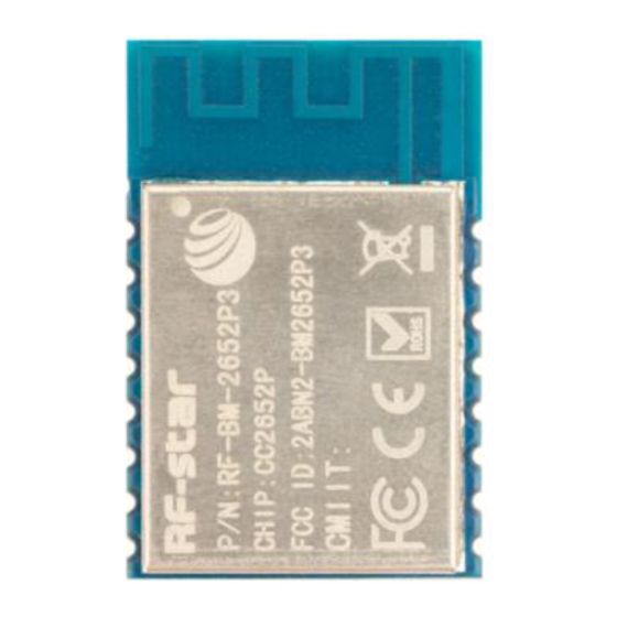
RF-BM-2652P3 www.szrfstar.com V1.0 - Feb., 2021 4 Application, Implementation, and Layout 4.1 Module Photos Figure 3. Photos of RF-BM-2652P3 4.2 Recommended PCB Footprint Figure 4. Recommended PCB Footprint of RF-BM-2652P3 Shenzhen RF-star Technology Co., Ltd. Page 11 of 22... -
Page 12: Schematic Diagram
The inverted-F antenna position on PCB is free-space electromagnetic radiation. The location and layout of the antenna are key factors to increase the data rate and transmission range. Therefore, the layout of the module antenna location and routing is recommended as follows: Shenzhen RF-star Technology Co., Ltd. Page 12 of 22... -
Page 13: Basic Operation Of Hardware Design
6. Assuming that there are devices with large electromagnetic interference around the module, which will greatly affect the module performance. It is recommended to stay away from the module according to the strength of the Shenzhen RF-star Technology Co., Ltd. Page 13 of 22... -
Page 14: Trouble Shooting
4.6.3 High Bit Error Rate 1. There are co-channel signal interferences nearby. It is recommended to be away from the interference sources or modify the frequency and channel to avoid interferences. Shenzhen RF-star Technology Co., Ltd. Page 14 of 22... -
Page 15: Electrostatics Discharge Warnings
3. If the extension wire or feeder wire is of poor quality or too long, the bit error rate will be high. 4.7 Electrostatics Discharge Warnings The module will be damaged by the discharge of static. RF-star suggests that all modules should follow the 3 precautions below: 1. - Page 16 RF-BM-2652P3 www.szrfstar.com V1.0 - Feb., 2021 Figure 5. Recommended Reflow for Lead-Free Solder Shenzhen RF-star Technology Co., Ltd. Page 16 of 22...
-
Page 17: Optional Package Specification
The default package method is . If you need the modules to be shipped by tape & reel, pls contact us in advance. Figure 6. Default Package by Tray Shenzhen RF-star Technology Co., Ltd. Page 17 of 22... - Page 18 RF-BM-2652P3 www.szrfstar.com V1.0 - Feb., 2021 Figure 7. Package by Tape & Reel Shenzhen RF-star Technology Co., Ltd. Page 18 of 22...
-
Page 19: Certification
(2) this device must accept any interference received, including interference that may cause undesired operation. FCC Identifier: 2ABN2-2652P3 Figure 8. FCC Certificate 6.2 CE Figure 9. CE Certificate Shenzhen RF-star Technology Co., Ltd. Page 19 of 22... - Page 20 RF-BM-2652P3 www.szrfstar.com V1.0 - Feb., 2021 6.3 RoHS RoHS Report No.:C210630006001-1 Figure 10. RoHS Certificate Shenzhen RF-star Technology Co., Ltd. Page 20 of 22...
- Page 21 1. The document will be optimized and updated from time to time. Before using this document, please make sure it is the latest version. 2. To obtain the latest document, please download it from the official website: www.rfstariot.com www.szrfstar.com. Shenzhen RF-star Technology Co., Ltd. Page 21 of 22...
- Page 22 RF-BM-2652P3 www.szrfstar.com V1.0 - Feb., 2021 8 Contact Us SHENZHEN RF-STAR TECHNOLOGY CO., LTD. Shenzhen HQ: Add.: C601, Skyworth Building, High-tech Park, Nanshan District, Shenzhen, Guangdong, China, 518057 Tel.: 86-755-8632 9829 Chengdu Branch: Add.: N2-1604, Global Center, North No. 1700, Tianfu Avenue, Hi-Tech District, Chengdu, Sichuan, China, 610095 Tel.: 86-28-8692 5399...
Need help?
Do you have a question about the SimpleLink RF-BM-2652P3 CC2652P and is the answer not in the manual?
Questions and answers