
Related Manuals for RF-Star RF-BM-BG22A1(I)


Summary of Contents for RF-Star RF-BM-BG22A1(I)
- Page 1 RF-BM-BG22A1(I) EFR32BG22C112 Bluetooth 5.2 Low Energy Module Version 1.3 Shenzhen RF-star Technology Co., Ltd. August 12 , 2022...
-
Page 2: Silicon Labs Ble Module List
2. All of the modules are based on Silicon Labs EFR32BG22 SoC series. Because the EFR32BG22 series ICs are compatible in package, pins, and peripherals, those modules are pin-to-pin compatible with each other if there are the same version of RF-star hardware version. Shenzhen RF-star Technology Co., Ltd. - Page 3 4. The transmission range is the longest distance obtained by testing the module's maximum transmission power in an open and interference-free environment in sunny weather. 5. Click the picture to buy modules. Shenzhen RF-star Technology Co., Ltd. Page 2 of 31...
-
Page 4: Device Overview
S, EUART and PDM. It features low power consumption, compact size, robust connection distance, and rigid reliability. 1.27-mm pitch stamp stick package for easy assembling and cost- effective PCB design. As for the firmware, it can be preprogrammed with an RF-star BLE5.0 serial communication protocol for simple programming. -
Page 5: Applications
Low-Pass Antenna Filter Half-Hole Switch ANT Pin Reset Power Supply DC-DC mode: 2.2 V to 3.8 V Bypass mode: 1.8 V to 3.8 V Figure 1. Functional Block Diagram of RF-BM-BG22A1(I) Shenzhen RF-star Technology Co., Ltd. Page 4 of 31... -
Page 6: Part Number Conventions
Antenna Type I: IPEX Connector IC Code Company Name EFR32BG22C112 RF-STAR Module Version The A HW Version Chipset Wireless Type Bluetooth Module EFR32BG22 Series Figure 2. Part Number Conventions of RF-BM-BG22A1(I) Shenzhen RF-star Technology Co., Ltd. Page 5 of 31... -
Page 7: Table Of Contents
5.4.3 External Antenna Design Recommendation of the Half-Hole ANT Pin ......20 5.4.4 IPEX Connector Specification ......................21 5.5 Basic Operation of Hardware Design ...................... 22 5.6 Trouble Shooting .............................. 23 Shenzhen RF-star Technology Co., Ltd. Page 6 of 31... -
Page 8: Table Of Figures
Figure 14. Specification of IPEX Wire ......................22 Figure 15. Recommended Reflow for Lead-Free Solder ................. 25 Figure 16. Default Package by Tray ......................... 26 Figure 17. Package by Tape & Reel ........................ 27 Shenzhen RF-star Technology Co., Ltd. Page 7 of 31... -
Page 9: Table Of Tables
Table 3. Recommended Operating Conditions of RF-BM-BG22A1(I) ..........12 Table 4. Handling Ratings of RF-BM-BG22A1(I) ..................12 Table 5. Current Consumption of RF-BM-BG22A1(I) ................12 Table 6. Temperature Table of Soldering and Reflow ................24 Shenzhen RF-star Technology Co., Ltd. Page 8 of 31... -
Page 10: Module Configuration And Functions
RF-BM-BG22A1: 70 m (@ PCB antenna) Transmission Range in Open Air RF-BM-BG22A1I: 120 m (@ external PCB antenna) -40 ℃ ~ +85 ℃ Operating Temperature Storage Temperature -40 ℃ ~ +125 ℃ Shenzhen RF-star Technology Co., Ltd. Page 9 of 31... -
Page 11: Module Pin Diagram
Pin Type Description EXT_ANT External antenna pin. PB02 PB02 GPIO PB01 PB01 GPIO PB00 PB00 GPIO PA00 PA00 GPIO GPIO PA03 PA03 PA04 PA04 GPIO GPIO PA05 PA05 PA06 PA06 GPIO Ground Shenzhen RF-star Technology Co., Ltd. Page 10 of 31... - Page 12 2.2 V ~ 3.8 V, recommended to 3.3 V GPIO PD01 PD01 PD00 PD00 GPIO PC00 PC00 GPIO PC01 PC01 GPIO PC02 PC02 GPIO GPIO PC03 PC03 PC04 PC04 GPIO GPIO PC05 PC05 Ground Shenzhen RF-star Technology Co., Ltd. Page 11 of 31...
-
Page 13: Specifications
FLUKE15B+ multimeter, load connects to DSA1030 spectrum analyzer, offset: 0.2, RBW = 100 KHz 1 A Stand-by Set Tx Power Actual Tx Power Actual Current Transmitting Current 0 dBm -0.5 dBm 4.0 mA Receiving Current 2.5 mA Shenzhen RF-star Technology Co., Ltd. Page 12 of 31... - Page 14 RF-BM-BG22A1(I) www.szrfstar.com V1.3 - Aug., 2022 Note: The test method is closely related to the current. For example, the output load antenna is different from the standard 50 Ω test data. Shenzhen RF-star Technology Co., Ltd. Page 13 of 31...
-
Page 15: Setting Of Frequency Offset Register
Oen the project, find the Project Explorer window, and open the project folder, as shown in the following figure. Then choose the config folder, find the sl_device_init_hfxo_config.h file, and double-click to open it, as shown in the figure below. Shenzhen RF-star Technology Co., Ltd. Page 14 of 31... - Page 16 Find SL_DEVICE_INIT_HFXO_CTUNE, the official default value of SiliconLabs is 140, RF-star changes it to 72 according to the requirements of the development board hardware RF part. Remark: This is the value for RF-star’s standard EFR32BG22 series modules, the value of the other customized products needs to be confirmed.
-
Page 17: Application, Implementation, And Layout
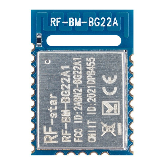
RF-BM-BG22A1(I) www.szrfstar.com V1.3 - Aug., 2022 5 Application, Implementation, and Layout 5.1 Module Photos RF-BM-BG22A1 RF-BM-BG22A1I Figure 4. Photos of RF-BM-BG22A1(I) 5.2 Recommended PCB Footprint RF-BM-BG22A1 Shenzhen RF-star Technology Co., Ltd. Page 16 of 31... -
Page 18: Figure 5. Recommended Pcb Footprint Of Rf-Bm-Bg22A1(I) (Mm)
RF-BM-BG22A1(I) www.szrfstar.com V1.3 - Aug., 2022 RF-BM-BG22A1I Figure 5. Recommended PCB Footprint of RF-BM-BG22A1(I) (mm) Shenzhen RF-star Technology Co., Ltd. Page 17 of 31... -
Page 19: Schematic Diagram
Figure 6. Schematic Diagram of RF-BM-BG22A1(I) 5.4 Antenna 5.4.1 Antenna Design Recommendation 1. The antenna installation structure has a great influence on the module performance. It is necessary to ensure the Shenzhen RF-star Technology Co., Ltd. Page 18 of 31... -
Page 20: Antenna Output Mode Modification
, and R1 (0 Ω) is well welded. If you want to use the external antenna by the ANT pin, pls disconnect the R1. The location of R1 is shown in the figure below. Figure 8. Antenna Output Mode Change of RF-BM-BG22A1 Shenzhen RF-star Technology Co., Ltd. Page 19 of 31... -
Page 21: External Antenna Design Recommendation Of The Half-Hole Ant Pin
The traces are as short as possible, and 135° or arc traces are used as much as possible. No vias are used to change layers. More GND vias are placed around the RF traces. Figure 10. Reference Design of the External Antenna Figure 11. Reference Design of the External Antenna Traces Shenzhen RF-star Technology Co., Ltd. Page 20 of 31... -
Page 22: Ipex Connector Specification
Figure 12. SI9000 Impedance Calculation Diagram 5.4.4 IPEX Connector Specification RF-BM-BG22A1I module is integrated the IPEX version 1 antenna seat, the specification of the antenna seat is as follows: Figure 13. Specification of Antenna Seat Shenzhen RF-star Technology Co., Ltd. Page 21 of 31... -
Page 23: Basic Operation Of Hardware Design
6. Assuming that there are devices with large electromagnetic interference around the module, which will greatly affect the module performance. It is recommended to stay away from the module according to the strength of the interference. If circumstances permit, appropriate isolation and shielding can be done. Shenzhen RF-star Technology Co., Ltd. Page 22 of 31... -
Page 24: Trouble Shooting
1. There are co-channel signal interferences nearby. It is recommended to be away from the interference sources or modify the frequency and channel to avoid interferences. 2. The unsatisfactory power supply may also cause garbled. It is necessary to ensure the power supply's reliability. Shenzhen RF-star Technology Co., Ltd. Page 23 of 31... -
Page 25: Electrostatics Discharge Warnings
3. If the extension wire or feeder wire is of poor quality or too long, the bit error rate will be high. 5.7 Electrostatics Discharge Warnings The module will be damaged by the discharge of static. RF-star suggests that all modules should follow the 3 precautions below: 1. -
Page 26: Figure 15. Recommended Reflow For Lead-Free Solder
RF-BM-BG22A1(I) www.szrfstar.com V1.3 - Aug., 2022 Figure 15. Recommended Reflow for Lead-Free Solder Shenzhen RF-star Technology Co., Ltd. Page 25 of 31... -
Page 27: Optional Package Specification
The default package method is . If you need the modules to be shipped by tape & reel, pls contact us in advance. Figure 16. Default Package by Tray Shenzhen RF-star Technology Co., Ltd. Page 26 of 31... -
Page 28: Figure 17. Package By Tape & Reel
RF-BM-BG22A1(I) www.szrfstar.com V1.3 - Aug., 2022 Figure 17. Package by Tape & Reel Shenzhen RF-star Technology Co., Ltd. Page 27 of 31... -
Page 29: Certification
(2) this device must accept any interference received, including interference that may cause undesired operation. FCC ID: 2ABN2-BG22A1 Figure 18. FCC certificate of RF-BM-BG22A1 6.2 CE Figure 19. CE certificate of RF-BM-BG22A1 Shenzhen RF-star Technology Co., Ltd. Page 28 of 31... -
Page 30: Srrc
RF-BM-BG22A1(I) www.szrfstar.com V1.3 - Aug., 2022 6.3 SRRC SRRC CMIIT ID: 2021DP8455 Figure 20. SRRC certificate of RF-BM-BG22A1 6.4 RoHS Figure 21. RoHS certificate of RF-BM-BG22A1 Shenzhen RF-star Technology Co., Ltd. Page 29 of 31... -
Page 31: Revision History
1. The document will be optimized and updated from time to time. Before using this document, please make sure it is the latest version. 2. To obtain the latest document, please download it from the official website: www.rfstariot.com and www.szrfstar.com. Shenzhen RF-star Technology Co., Ltd. Page 30 of 31... -
Page 32: Contact Us
RF-BM-BG22A1(I) www.szrfstar.com V1.3 - Aug., 2022 8 Contact Us SHENZHEN RF-STAR TECHNOLOGY CO., LTD. Shenzhen HQ: Add.: C601, Skyworth Building, High-tech Park, Nanshan District, Shenzhen, Guangdong, China, 518057 Tel.: 86-755-3695 3756 Chengdu Branch: Add.: N2-1604, Global Center, North No. 1700, Tianfu Avenue, Hi-Tech District, Chengdu, Sichuan, China, 610095 Tel.: 86-28-6577 5970...
Need help?
Do you have a question about the RF-BM-BG22A1(I) and is the answer not in the manual?
Questions and answers