Table of Contents

Subscribe to Our Youtube Channel
Related Manuals for RF-Star SimpleLink RF-TI1352B1 CC1352R


Summary of Contents for RF-Star SimpleLink RF-TI1352B1 CC1352R
- Page 1 RF-TI1352B1 CC1352R SimpleLink High- Performance Sub-1G + 2.4 G Dual-band Module Version 1.0 Shenzhen RF-star Technology Co., Ltd. Apr. 14 , 2020 All rights reserved. Those responsible for unauthorized reproduction will be prosecuted.
-
Page 2: Device Overview
- 28 GPIOs, digital peripherals can be routed - -110 dBm @ Sub-1 GHz (50 kbps) to any GPIOs - -105 dBm for Bluetooth 125 kbps (LE coded - 4× 32-bit or 8× 16-bit general-purpose PHY) Shenzhen RF-star Technology Co., Ltd. Page 1 of 23... -
Page 3: Applications
• Smart plug and metering • Building automation • Home appliances • Sensor networks • Sensor nodes • Medical devices • Security systems • Gaming controller • Industrial control • Remote controls Shenzhen RF-star Technology Co., Ltd. Page 2 of 23... -
Page 4: Functional Block Diagram
The part numbers are of the form of RF-TI1352B1 where the fields are defined as follows: 1352 RF-STAR Module Version The First Version Company Name Chip Manufacturer Chipset TI CC1352R Figure 2. Part Number Conventions of RF-TI1352B1 Shenzhen RF-star Technology Co., Ltd. Page 3 of 23... -
Page 5: Table Of Contents
4.7.2 Vulnerable Module ..........................17 4.7.3 High Bit Error Rate ..........................17 4.8 Electrostatics Discharge Warnings ......................17 4.9 Soldering and Reflow Condition ......................... 17 5 Optional Package Specification ..........................19 Shenzhen RF-star Technology Co., Ltd. Page 4 of 23... - Page 6 RF-TI1352B1 www.szrfstar.com V1.0 - Apr., 2020 6 Revision History ................................22 7 Contact Us ..................................23 Shenzhen RF-star Technology Co., Ltd. Page 5 of 23...
-
Page 7: Module Configuration And Functions
Thread, Zigbee®, Bluetooth® 5.3 Low Energy, IEEE 802.15.4g, IPv6-enabled Support Protocol smart objects, (6LoWPAN), MIOTY ® , Wireless M-Bus, Wi-SUN ® , KNX RF, Amazon Sidewalk, proprietary systems, SimpleLink ™ TI 15.4-Stack (Sub-1 Shenzhen RF-star Technology Co., Ltd. Page 6 of 23... -
Page 8: Module Pin Diagram
Type of Antenna IPEX connector, half-hole ANT pin -40 ℃ ~ +85 ℃ Operating Temperature -40 ℃ ~ +125 ℃ Storage Temperature 2.2 Module Pin Diagram Figure 3. Pin Diagram of RF-TI1352B1 Shenzhen RF-star Technology Co., Ltd. Page 7 of 23... -
Page 9: Pin Functions
Reset, active low. Internal pullup. RESET_N Digital DIO_16 Digital GPIO, JTAG_TDO, high-drive capability DIO_17 Digital GPIO, JTAG_TDI, high-drive capability DIO_18 Digital GPIO DIO_19 Digital GPIO DIO_20 Digital GPIO DIO_21 Digital GPIO DIO_22 Digital GPIO Shenzhen RF-star Technology Co., Ltd. Page 8 of 23... - Page 10 DIO_30 Digital or Analog GPIO, analog capability Ground Ground 2G4-OUT RF Out 2.4 GHz antenna pin out Antenna Ground Antenna Ground SUB-OUT RF Out Sub 1GHz antenna pin out Ground Ground Shenzhen RF-star Technology Co., Ltd. Page 9 of 23...
-
Page 11: Specifications
3.2 Handling Ratings Table 4. Handling Ratings of RF-TI1352B1 Condition Items Min. Typ. Max. Unit Tstg Storage Temperature +125 ℃ Human Body Model ±2000 Moisture Sensitivity Level Charged Device Model ±500 Shenzhen RF-star Technology Co., Ltd. Page 10 of 23... -
Page 12: Application, Implementation, And Layout
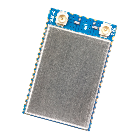
RF-TI1352B1 www.szrfstar.com V1.0 - Apr., 2020 4 Application, Implementation, and Layout 4.1 Module Photos Figure 4. Photos of RF-TI1352B1 4.2 Recommended PCB Footprint Figure 5. Recommended PCB Footprint of RF-TI1352B1 Shenzhen RF-star Technology Co., Ltd. Page 11 of 23... -
Page 13: Schematic Diagram
RF-TI1352B1 www.szrfstar.com V1.0 - Apr., 2020 4.3 Schematic Diagram Figure 6. Schematic Diagram of RF-TI1352B1 4.4 Reference Design Figure 7. Reference Design of RF-TI1352B1 Shenzhen RF-star Technology Co., Ltd. Page 12 of 23... -
Page 14: Antenna
The traces are as short as possible, and 135° or arc traces are used as much as possible. No vias are used to change layers. More GND vias are placed around the RF traces. Shenzhen RF-star Technology Co., Ltd. Page 13 of 23... - Page 15 Example: FR4 is a double-layer board with a thickness of 1.0 mm. Through calculation, the width of the trace is 0.8254 mm, and the spacing between traces and copper is 0.22 mm. Figure 11. SI9000 Impedance Calculation Diagram Shenzhen RF-star Technology Co., Ltd. Page 14 of 23...
-
Page 16: Ipex Connector Specification
1. It is recommended to offer the module a DC stabilized power supply, a tiny power supply ripple coefficient, and reliable ground. Please pay attention to the correct connection between the positive and negative poles of the power Shenzhen RF-star Technology Co., Ltd. Page 15 of 23... -
Page 17: Trouble Shooting
4. The incorrect power register set or the high data rate in the open air may shorten the communication distance. The higher the data rate, the closer the distance. Shenzhen RF-star Technology Co., Ltd. Page 16 of 23... -
Page 18: Vulnerable Module
3. If the extension wire or feeder wire is of poor quality or too long, the bit error rate will be high. 4.8 Electrostatics Discharge Warnings The module will be damaged by the discharge of static. RF-star suggests that all modules should follow the 3 precautions below: 1. - Page 19 Max. 6 ℃/s Time from 25 ℃ to Peak Temperature (t Max. 6 minutes Max. 8 minutes Time of Soldering Zone (t 20±10 s 20±10 s Figure 14. Recommended Reflow for Lead-Free Solder Shenzhen RF-star Technology Co., Ltd. Page 18 of 23...
-
Page 20: Optional Package Specification
V1.0 - Apr., 2020 5 Optional Package Specification by tray The default package method is . If you need the modules to be shipped by tape & reel, pls contact us in advance. Shenzhen RF-star Technology Co., Ltd. Page 19 of 23... - Page 21 RF-TI1352B1 www.szrfstar.com V1.0 - Apr., 2020 Figure 15. Default Package by Tray Shenzhen RF-star Technology Co., Ltd. Page 20 of 23...
- Page 22 RF-TI1352B1 www.szrfstar.com V1.0 - Apr., 2020 Figure 16. Package by Tape & Reel Shenzhen RF-star Technology Co., Ltd. Page 21 of 23...
- Page 23 1. The document will be optimized and updated from time to time. Before using this document, please make sure it is the latest version. 2. To obtain the latest document, please download it from the official website: www.rfstariot.com and www.szrfstar.com. Shenzhen RF-star Technology Co., Ltd. Page 22 of 23...
- Page 24 RF-TI1352B1 www.szrfstar.com V1.0 - Apr., 2020 7 Contact Us SHENZHEN RF-STAR TECHNOLOGY CO., LTD. Shenzhen HQ: Add.: C601, Skyworth Building, High-tech Park, Nanshan District, Shenzhen, Guangdong, China, 518057 Tel.: 86-755-8632 9829 Chengdu Branch: Add.: N2-1604, Global Center, North No. 1700, Tianfu Avenue, Hi-Tech District, Chengdu, Sichuan, China, 610095 Tel.: 86-28-8692 5399...
Need help?
Do you have a question about the SimpleLink RF-TI1352B1 CC1352R and is the answer not in the manual?
Questions and answers