
Related Manuals for RF-Star RF-83SH


Summary of Contents for RF-Star RF-83SH
- Page 1 RF-83SH SX1276 868 MHz & 915 MHz LoRa Module Version 1.3 Shenzhen RF-star Technology Co., Ltd. Jan. 19 , 2020...
-
Page 2: Rf-Star Lora Module List
1. The communication distance is the longest distance obtained by testing the module's maximum transmission power in an open and interference-free environment in sunny weather. 2. Click the picture to jump to buy modules. Shenzhen RF-star Technology Co., Ltd. Page 1 of 19... -
Page 3: Device Overview
1.1 Description RF-83SH module is a LoRa spread spectrum module, with operating frequency of 868 MHz ~ 893 MHz & 900 MHz ~ 931 MHz, based on the Semtech SX1276. It is a wireless SPI transceiver module with 3.3 V TTL level output. RF-star LoRa module features with ultra-long range spread spectrum communication, concentrated power density, high interference immunity ability, confidentiality, and significantly lower current consumption. -
Page 4: Functional Block Diagram
TCXO 32.0 MHz LNA LDO Figure 1. Functional Block Diagram of RF-83SH 1.5 Part Number Conventions The part numbers are of the form of RF-83SH where the fields are defined as follows: RF 8 Package Mode Company Name Half-hole Mode... -
Page 5: Table Of Contents
RF-83SH www.szrfstar.com V1.3 - Jan., 2020 Table of Contents RF-star LoRa Module List ............................... 1 1 Device Overview ................................2 1.1 Description ................................2 1.2 Key Features ............................... 2 1.3 Applications ................................2 1.4 Functional Block Diagram ..........................3 1.5 Part Number Conventions ..........................3 Table of Contents ................................ -
Page 6: Table Of Figures
Figure 3. Pin Diagram of RF-83SH ........................7 Figure 4. Photos of RF-83SH ..........................11 Figure 5. Recommended PCB Footprint of RF-83SH (mm) ..............11 Figure 6. Schematic Diagram of RF-83SH ....................12 Figure 7. Reference Design of the Connection between MCU and Module ........13 Figure 8. -
Page 7: Module Configuration And Functions
RF-83SH www.szrfstar.com V1.3 - Jan., 2020 2 Module Configuration and Functions 2.1 Module Parameters Table 1. Parameters of RF-83SH Chipset Semtech SX1276 Supply Power Voltage 3.3 V ~ 5.2 V, recommended to 5.0 V 862 MHz ~ 893 MHz, typical: 868 MHz... -
Page 8: Module Pin Diagram
RF-83SH www.szrfstar.com V1.3 - Jan., 2020 2.2 Module Pin Diagram Figure 3. Pin Diagram of RF-83SH 2.3 Pin Functions Table 2. Pin Functions of RF-83SH Name Chip Pin Pin Type Description Ground Digital I/O, software configured DIO5 DIO5 DIO4 DIO4... - Page 9 Module chip select pin for starting SPI communication TXEN TXEN RF switch pin control, high in RX, low in TX. RXEN RXEN RF switch pin control, high in TX, low in RX. Ground Antenna port Ground Ground Ground Shenzhen RF-star Technology Co., Ltd. Page 8 of 19...
-
Page 10: Specifications
Functional operation does not guarantee performance beyond the limits of the conditional parameter values in the table below. Long-term work beyond this limit will affect the reliability of the module more or less. Table 3. Recommended Operating Conditions of RF-83SH Items Condition Typ. - Page 11 RFOP = +20 dBm, on PA_BOOST RFOP = +17 dBm, on Supply current in Transmit mode with PA_BOOST impedance matching RFOP = +13 dBm, on RFO_LF/HF pin RFOP = +7 dBm, on RFO_LF/HF pin Shenzhen RF-star Technology Co., Ltd. Page 10 of 19...
-
Page 12: Application, Implementation, And Layout
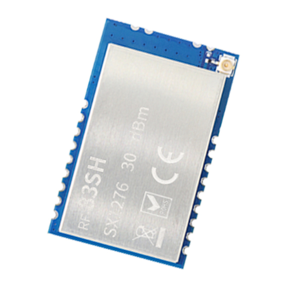
RF-83SH www.szrfstar.com V1.3 - Jan., 2020 4 Application, Implementation, and Layout 4.1 Module Photos Figure 4. Photos of RF-83SH 4.2 Recommended PCB Footprint Figure 5. Recommended PCB Footprint of RF-83SH (mm) Shenzhen RF-star Technology Co., Ltd. Page 11 of 19... -
Page 13: Schematic Diagram
RF-83SH www.szrfstar.com V1.3 - Jan., 2020 4.3 Schematic Diagram Figure 6. Schematic Diagram of RF-83SH Shenzhen RF-star Technology Co., Ltd. Page 12 of 19... -
Page 14: Reference Design Of The Connection Between Mcu And Module
Bottom Layer (all copper is well grounded). 5. Assuming that the module is soldered or placed in the Top Layer, it is also wrong to randomly route the Bottom Layer Shenzhen RF-star Technology Co., Ltd. Page 13 of 19... -
Page 15: Software Written
1. When there is a linear communication obstacle, the communication distance will be correspondingly weakened. Temperature, humidity, and co-channel interference will lead to an increase in communication packet loss rate. The Shenzhen RF-star Technology Co., Ltd. Page 14 of 19... -
Page 16: Vulnerable Module
4. If the extension wire or feeder wire is of poor quality or too long, the bit error rate will be high. 4.7 Electrostatics Discharge Warnings The module will be damaged for the discharge of static. RF-star suggest that all modules should follow the 3 precautions below: 1. -
Page 17: Soldering And Reflow Condition
Time from 25 ℃ to Peak Temperature (t Max. 6 minutes Max. 8 minutes 20±10 s 20±10 s Time of Soldering Zone (t Figure 8. Recommended Reflow for Lead Free Solder Shenzhen RF-star Technology Co., Ltd. Page 16 of 19... -
Page 18: Optional Packaging
RF-83SH www.szrfstar.com V1.3 - Jan., 2020 4.9 Optional Packaging Figure 9. Optional Packaging Mode Note: Default tray packaging. Shenzhen RF-star Technology Co., Ltd. Page 17 of 19... -
Page 19: Revision History
1. The document will be optimized and updated from time to time. Before using this document, please make sure it is the latest version. 2. To obtain the latest document, please download it from the official website: www.szrfstar.com. Shenzhen RF-star Technology Co., Ltd. Page 18 of 19... -
Page 20: Contact Us
RF-83SH www.szrfstar.com V1.3 - Jan., 2020 6 Contact Us SHENZHEN RF-STAR TECHNOLOGY CO., LTD. Shenzhen HQ: Add.: Room 601, Block C, Skyworth Building, High-tech Park, Nanshan District, Shenzhen, Guangdong, China Tel.: 86-755-3695 3756 Chengdu Branch: Add.: No. B3-03, Building No.1, Incubation Park, High-Tech District, Chengdu, Sichuan, China, 610000 Tel.: 86-28-6577 5970...
Need help?
Do you have a question about the RF-83SH and is the answer not in the manual?
Questions and answers