
Related Manuals for IFM Electronic ASinterface AC1309


Summary of Contents for IFM Electronic ASinterface AC1309
- Page 1 Montageanleitung Installation instructions Notice de montage AS-i CONTROLLER CONTRÔLEUR AS-i AC1309/AC1310...
-
Page 2: Bestimmungsgemäße Verwendung
Bestimmungsgemäße Verwendung • Der Controller integriert einen oder zwei AS-i Master (AC1309/ AC1310, beide nach AS-i-Version 2.1), eine Kleinsteuerung und eine Ethernet-Schnittstelle • Er steuert den Datenaustausch zur Sensor- /Aktuator-Ebene • verarbeitet die Peripheriedaten im integrierten Prozessor (Signalvor- verarbeitung) • arbeitet als stand-alone-Steuerung mit Datenaustausch zum PC (Visualisierung) •... -
Page 3: Elektrischer Anschluß
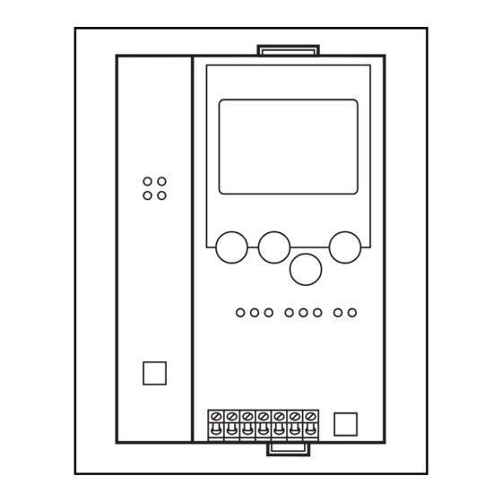
Elektrischer Anschluß Schalten Sie die Anlage spannungsfrei. Schließen Sie das Gerät entsprechend der Klemmenbeschriftung an. Verbinden Sie nie- mals die Minuspotentiale untereinander oder Minuspotentiale und FE-Anschluß. Stellen Sie eine elektrisch sichere Erdverbin- dung zwischen AS-i Controller (Klemme FE) und Gerät-Erdan- schluß... - Page 4 rot blinkend 4Hz: Interner Fehler Ethernet-Schnitt- stelle rot leuchtet: doppelte IP-Adresse erkannt LED Modbus/TCP connections: zyklischer Datenaustausch über Modbus/TCP Protokoll LED Link to Ethernet: Controller ist mit einem Ether- net-Netzwerk verbunden LED Transmission activity: Blinkt grün bei jedem übertra- genem Datenpaket LED-Anzeigen und Anschlußbelegung Display...
-
Page 5: Betrieb
Kontrasteinstellung Sie können den Kontrast direkt durch gleichzeitiges Drücken der rech- ten Taste mit der ∆-Taste (Darstellung ist zu hell) bzw. der ∇-Taste (...zu dunkel) verstellen. ifm electronic ifm electronic Controller E Controller E MENU USER MENU USER ∆ ∆... -
Page 6: Menü-Übersicht
Sie im Startdisplay die Menüpunktes, indem Sie die Tasten ∆ oder ∇ drücken. linke Taste „MENU“ drücken. Drücken Sie die Tasten gleichzei- tig, um zwischen deutschem und englischem Menü zu wechseln. ifm electronic ifm electronic Controller E Controller E MENU USER MENU USER ∆... - Page 7 O System Setup (Einstellung des Controller Gerätes) ∇ Baudrate der seriellen Programmierschnittstelle ∇ IP Adresse der Ethernet Programmierschnittstelle (optional) ∇ Eingabe des Passwortes zur Freigabe von Ände- rungen in der Systemkonfiguration ∇ Update der Firmware des Controller (spezielle Programmiersoftware erforderlich) O System Info (Geräte Informationen) ∇...
- Page 8 O Slave Setup (Detaillierte Informationen über die angeschlossenen AS-i Slaves) ∇ Digitale bzw. analoge Ein-/Ausgänge der ange- schlossenen AS-i Slaves ∇ Aktuelle und projektierte Parameter der ange- schlossenen AS-i Slaves ∇ Aktuelle und projektierte I /O- und ID-Codes der angeschlossenen AS-i Slaves ∇...
-
Page 9: Function And Features
Function and features • The controller integrates AS-i masters (AC1309/AC1310, both in accordance with the AS-i version 2.1), a mini controller and an Ethernet interface. • It controls the exchange of data to the sensor / actuator level • processes the peripheral data in the integrated processor (signal pre- processing) •... -
Page 10: Electrical Connection
(terminal FE) and ground of the unit. Supply the controller with a 24V DC voltage (20 ... 30V PELV), e.g. from the 24V power supply DN2011 of ifm electronic. The connection is made to the terminals +24V and 0V. Operating and indicating elements... - Page 11 red flashing 4Hz: internal fault Ethernet interface red flashing: double IP address recognised LED Modbus/TCP connections: cyclical data exchange via Mod- bus /TCP protocol LED Link to Ethernet: controller is connected to an Ethernet system LED Transmission activity: flashing green for every data package transferred LED indicators and pin connection...
-
Page 12: Contrast Setting
Contrast setting The contrast can be directly changed by simultaneously pressing the right button and the ∆-button (too bright) or the ∇−button (too dark). ifm electronic ifm electronic Controller E Controller E MENU USER MENU USER ∆ ∆ decrease contrast... -
Page 13: Menu Overview
To navigate within a menu point press the button ∆ or ∇. the left button "MENU" in the start display. Press the buttons simultaneously to switch between the German and English menu. ifm electronic ifm electronic Controller E Controller E MENU USER MENU USER ∆... - Page 14 O System setup (Setting of the controller device) ∇ Baud rate of the serial programming interface ∇ IP address of the Ethernet programming interface (optional) ∇ Input of the password to enable changes in the system configuration ∇ Update of the controller e firmware (special pro- gramming software required) O System info (Device information)
- Page 15 O Slave setup (Details about the connected AS-i slaves) ∇ Digital or analogue inputs/outputs of the connec- ted AS-i slaves ∇ Current and projected parameters of the connec- ted AS-i slaves ∇ Current and projected I/O and ID codes of the connected AS-i slaves ∇...
-
Page 16: Fonctionnement Et Caractéristiques
Fonctionnement et caractéristiques • Le contrôleur intègre un ou deux maîtres AS-i (AC1309/AC1310, les deux selon la version AS-i 2.1), une unité de prétraitement et une interface Ethernet. • Il contrôle l'échange de données avec le niveau capteurs/ action- neurs, •... -
Page 17: Raccordement Électrique
(borne FE) et la terre de l'appareil. Alimenter le contrôleur en 24V DC (20 ... 30V TBTP), par ex. via l'ali- mentation 24V DN2011 d'ifm electronic. Le raccordement se fait aux bornes +24V et 0V. Eléments de service et d'indication L'état du maître (AC1305) / des maîtres (AC1306) et du système rac-... - Page 18 rouge clignotant 4Hz: défaut interne interface Ethernet rouge allumée: adresse IP double reconnue LED Modbus/TCP connections: échange de données cyclique via protocole Modbus/TCP LED Link to Ethernet: Controller est raccordé à un système Ethernet LED Transmission activity: clignote en vert pour chaque paquet de données transmis Voyants LED et raccordement des bornes...
-
Page 19: Réglage Du Contraste
Réglage du contraste Le contraste peut être modifié directement en appuyant simultané- ment sur le bouton droit et le bouton ∆ (trop clair) ou le bouton ∇ (trop foncé). ifm electronic ifm electronic Controller E Controller E MENU USER MENU USER ∆... -
Page 20: Aperçu Du Menu
"MENU" dans l'écran de départ. point de menu. Appuyez sur les boutons-poussoirs simultané- ment pour changer entre le menu allemand et anglais. ifm electronic ifm electronic Controller E Controller E MENU USER MENU USER ∆... - Page 21 O System Setup (Réglage du contrôleur ∇ Débit de transmission de l'interface de program- mation série ∇ Adresse IP de l'interface de programmation Ethernet (option) ∇ Saisie du mot de passe permettant de modifier la configuration du système ∇ Mise à jour du firmware du contrôleur (logiciel de programmation spécifique nécessaire) O System Info (Informations sur l'appareil)
- Page 22 O Slave Setup (Informations détaillées sur les esclaves AS-i raccordés) ∇ Entrées/sorties TOR ou analogiques des esclaves AS-i raccordés ∇ Paramètres actuels et présélectionnés des esclaves AS-i raccordés ∇ Codes E/S et ID actuels et présélectionnés des esclaves AS-i raccordés ∇...
- Page 23 Maßzeichnung Scale drawing Schéma d’encombrement PAGE...
Need help?
Do you have a question about the ASinterface AC1309 and is the answer not in the manual?
Questions and answers