Table of Contents
Advertisement
Quick Links
Model 74000-53
(US & Canada only) Toll Free 1-800-MASTERFLEX • 1-800-637-3739
(Outside US & Canada) 1-847-549-7600 • 1-847-381-7050
www.masterflex.com • techinfo@masterflex.com
®
Operating and Installation Manual:
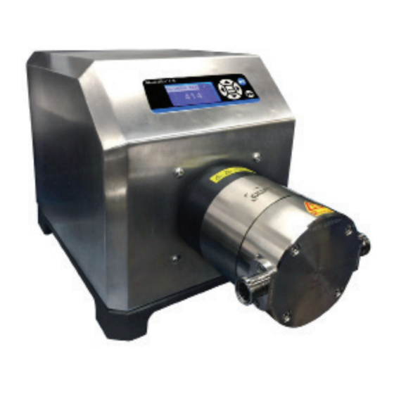
QUATTROFLOW 1200S
MULTIPLE-USE STAINLESS STEEL
QUATERNARY PUMP 4 PISTON
DIAPHRAGM PUMP
Model No.
74000-53
Edition 05
A-1299-7370
Advertisement
Table of Contents

Related Manuals for Masterflex QUATTROFLOW 1200S


Summary of Contents for Masterflex QUATTROFLOW 1200S
- Page 1 Operating and Installation Manual: QUATTROFLOW 1200S MULTIPLE-USE STAINLESS STEEL QUATERNARY PUMP 4 PISTON DIAPHRAGM PUMP Model No. 74000-53 Model 74000-53 Edition 05 A-1299-7370 (US & Canada only) Toll Free 1-800-MASTERFLEX • 1-800-637-3739 (Outside US & Canada) 1-847-549-7600 • 1-847-381-7050 www.masterflex.com • techinfo@masterflex.com...
- Page 2 Preface © 2019 Cole-Parmer Instrument Company. All rights reserved. Masterflex — Reg TM Cole-Parmer Instrument Company. © 2019 ALMATEC. Quattroflow is a trademark of ALMATEC MASCHINBAU Gmbh. ® Trademark bearing the symbol in this publication are registered in the U.S. and in other countries.
- Page 3 This product is not designed for, nor intended for use in hazardous duty areas as defined by ATEX or the NEC (National Electrical Code); including, but not limited to use with flammable liquids. Consult the factory for products suitable for these types of applications. Masterflex A-1299-7370...
-
Page 5: Table Of Contents
TECHNICAL DATA ..........Masterflex... -
Page 7: General
UV-radiation and mechanical infl uences. Th e following storage conditions are recommended: -Steady ventilated, dust and vibration free storage room -Ambient temperature between 15°C (59°F) and 25°C (77°F) with a relative humidity below 65%. -Prevention of direct thermal infl uences (sun, heating). Masterflex A-1299-7370... -
Page 8: Labeling Of The Pump
Th e type label of each Quattrofl ow pump can be seen on the bottom of the pump. Th e serial number of the pump head is fi xed the bottom of the pump. Masterflex Pump Drive For further information on the pump drive system see within this flash drive or on the web. -
Page 9: Qf1200 S Pump Description
Th e stroke of the piston is determined by the angle of the eccentric. Th ere are eccentric shafts with 5° available. Range of fl ow rate: 5°eccentric shaft: approximate 20-11200 L/hr In Gallons: 5˚ eccentric shaft: approximate 5.3- 317 gph Masterflex A-1299-7370... -
Page 10: Start-Up
Pay attention to the required space needed for assembly and disas- sembly of the pump chamber. During start-up pay attention to the warning and safety instructions of this manual. A-1299-7370 Masterflex... -
Page 11: Cleaning (Cip)
30 min. Follow the instructions from the autoclave manufacturer. Please make sure that the pump chamber is not placed on the clamp ring during the autoclave process. The clamp ring should not be loaded during autoclaving. Masterflex A-1299-7370... -
Page 12: Steaming In Place (Sip)
Depending on the SIP conditions it may be necessary to shorten the maintenance intervals for the elastomers signifi cantly. Tightening torques (10 Nm, 7.4 lb-ft) of the front bolts of the pump chamber must be checked after each SIP cycle. 2-4 A-1299-7370 Masterflex... -
Page 13: Safety
- Leakages of dangerous products have to be handled without any danger for persons and environment. Statutory regulations must be observed. - Dangers by electrical energy are to be excluded (for details please refer to the regulations of the VDE and the local energy supply associations). Masterflex A-1299-7370... -
Page 14: Safe Maintenance, Inspection, And Mounting Operations
A safe operation of the pump is ensured only by an appropriate use according to Invalid Modes the specifi c data of the enclosed pump data sheet. Th e values limitations given in of Operation the data sheet must not be exceeded. Masterflex 3-2 A-1299-7370... -
Page 15: Additional Safety Warnings
• Operating the pump in humid or aggressive air can cause damages to the motor and control box. • Th e control box should not be exposed to spray/splash water or to heat sources. Masterflex A-1299-7370 3-3... - Page 16 1200 S must not be operated in explosion-proof areas. Special versions for “ATEX” applications are available. Please contact the manufacturer. Attention!- Inadmissible modes of operation, arbitrary reconstruction, spare parts production and/or any changes of the design (without permission of the manufacturer) may cancel the liability resulting there from. 3-4 A-1299-7370 Masterflex...
-
Page 17: Maintenance/Servicing
Elastomer parts 1000 h operating hours, Replacement of the elastomer parts (diaphragm, valves, and at least once a year (Contact Masterflex for order number). O-rings) Shaft-bearing-cap unit 1000 h operating hours, Replacement of the complete unit (Con- at least once a year tact Masterflex for order number). -
Page 18: Replacing Diaphragm, Valves, And O-Rings
Diaphragm with Supports Pull off the pump chamber Diaphragm Cover Outlet Valve Pump Housing Valve Plate ø O-ring 85 x 3 ø O-ring 45 x 3 Unscrew M4 x 6 Valve Plate Diaphragm Push Out inlet Valves Diaphragm Support 4-2 A-1299-7370 Masterflex... - Page 19 Ring Drive Unit Pump Chamber Pay attention to the following torque values: Image 10: Bolts pump chamber 10 Nm (7.4 lb-ft) Image 10: Bolts diaphragm cover housing 5 Nm (3.7 lb-ft) Image 12: Bolt clamping ring 6 Nm (4.4 lb-ft) Masterflex A-1299-7370...
- Page 20 Ring Drive Unit 2. Drive Housing Pull off the ring drive unit Bearing Housing Pull off the Pump Chamber Pull off the Shaft Bearing Cap Unit Bearing Housing ø 1. Unscrew the M5 x 35 with washer 4-4 A-1299-7370 Masterflex...
-
Page 21: Assembling Ring Drive
After the installation of the pump head (figure Image 8: Bolts pump chamber 10 Nm (7.4 lb-ft) 10), between both coupling halves has to be a Image 9: Bolt clamping ring 6 Nm (4.4 lb-ft) gap of 1.5 mm (0.079 - 0.118 in) A-1299-7370 4-5 Masterflex... -
Page 23: Troubleshooting
– replace the pump chamber O–rings between valve plate and pump housing are defective Align coupling accurately The clamping ring screw got loose – fix it! See Drive Manual Pump after SIP cooled down too fast slow cooling room temperature. A-1299-7370 Masterflex... -
Page 25: Performance Charts
If reducer gear drives are used: Pump rpm= motor rpm x reduction ratio Eccentric Shaft: 5° Frequency Motor [Hz] 1400 1200 1000 1000 1500 2000 Pump speed [RPM] 0 bar 3 bar 6 bar Frequency Motor [Hz] 1000 1500 2000 Pump speed [RPM] 0 psi 43 psi 87 psi A-1299-7370 Masterflex... -
Page 27: Technical Data
3/4” TC Flange Diameter 25 mm Internal Diameter 15.75 mm Connection Specification Outlet (standard) Connector 3/4” TC Flange Diameter 25 mm Internal Diameter 15.75 mm Position of Connectors In-line Number of Flow Directions Diameter Drive Shaft 17 mm A-1299-7370 Masterflex... - Page 28 Dimensions Pump with Motor and SS Housing: Length 445 mm (17.5 in) Width 280 mm (11 in) Height 330 mm (13 in) Weight Pump with Motor and Housing: Pump with Motor and SS Housing 49.3 kg (22.4 lbs) Masterflex 7-2 A-1299-7370...
- Page 29 ALMATEC Maschinenbau GmbH Carl-Friedrich-Gauss-Str. 5 D-47475 Kamp-Lintfort, Germany US & Canada only *EN809 manufactured by: Toll Free 1-800-MASTERFLEX | 1-800-637-3739 Cole-Parmer Instrument Company Outside US & Canada 28W092 Commercial Avenue, Barrington, IL 60010 1-847-549-7600 | 1-847-381-7050 techinfo@masterflex.com | www.masterflex.com...
Need help?
Do you have a question about the QUATTROFLOW 1200S and is the answer not in the manual?
Questions and answers