Table of Contents
Advertisement
Available languages
Available languages
Quick Links
®
®
The MASTERFLEX
C/L
Pump Systems are small peristaltic
pumps with integral drive motors and are intended for use with
a series of tubing sizes that provide flow rates in the range of
2.2 µL/min to 12.3 mL/min.
Model No.
Nº de modèle
Modellnummern
Modelo No.
Modello No.
77120-32
77120-42
77120-52
77120-62
1-800-MASTERFLEX (627-8373) (U.S. and Canada only) • 11 (847) 549-7600 (Outside U.S.)
(847) 549-7600 (Local) • www.masterflex.com • techinfo@coleparmer.com
Thermo Fisher Scientific
1-800-637-3739 (U.S. and Canada only) • 11 (847) 381-7050 (Outside U.S.)
(847) 381-7050 (Local) • www.thermoscientific.com • fluidhandling@thermoscientific.com
OPERATING MANUAL:
PUMP SYSTEM
MANUEL DE L'UTILISATEUR :
SYSTEME DE POMPAGE
BEDIENUNGSANLEITUNG:
PUMPENSYSTEM
MANUAL DE OPERACIÓN:
SISTEMA DE BOMBAS
MANUALE dI ISTRUZIONI:
SISTEMA POMPANTE
A-1299-1039
Edition 03
Advertisement
Chapters
Table of Contents

Related Manuals for Masterflex C/L Series


Summary of Contents for Masterflex C/L Series
- Page 1 77120-52 77120-62 A-1299-1039 Edition 03 1-800-MASTERFLEX (627-8373) (U.S. and Canada only) • 11 (847) 549-7600 (Outside U.S.) (847) 549-7600 (Local) • www.masterflex.com • techinfo@coleparmer.com Thermo Fisher Scientific 1-800-637-3739 (U.S. and Canada only) • 11 (847) 381-7050 (Outside U.S.) (847) 381-7050 (Local) • www.thermoscientific.com • fluidhandling@thermoscientific.com...
-
Page 2: Table Of Contents
PUMP SYSTEM TUBING FLOW RATES .......10 SAFETY PRECAUTIONS WARNING: Tubing breakage may result in fluid being sprayed from pump. Use appropriate measures to protect operator and equipment. CAUTION: Tubing for use with the MASTERFLEX ® ® Pump Systems is Microbore Autoanalysis Tubing. See Appendix A for specifics. -
Page 3: Introduction
INTRODUCTION The MASTERFLEX ® ® Pump System is designed to pump dispensing, analyzers, printing systems, controlled feeding fluid through Microbore tubing by means of peristaltic action and non-human infusion procedures. at very low flow rates. It is ideal for sanitizers, reagent... -
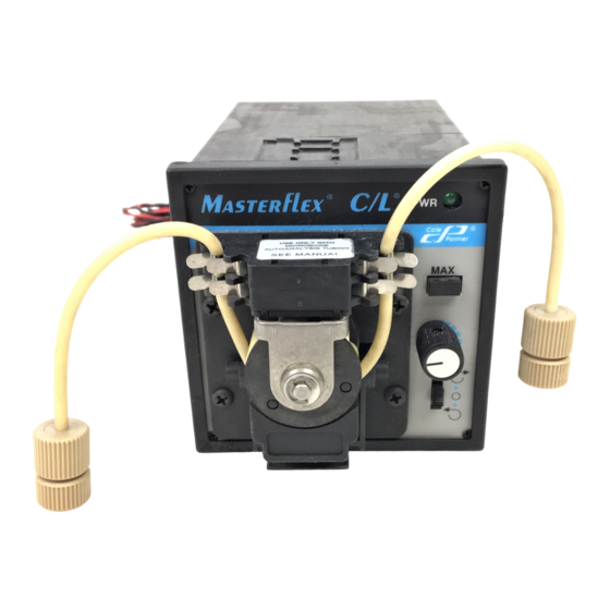
Page 4: General Description
Rotor contains six rollers for minimum pulsation. All units operate from an External DC Power Supply. The AC models are ® ® Figure 1. MASTERFLEX Pump System supplied with a Universal Power Supply, which provides a DC output for connection to the Pump Drive. -
Page 5: Setup
Remote Selecting Tubing Size Start/Stop Input Appendix A provides a list of tubing sizes which will work efficiently with the MASTERFLEX ® ® Pump System. This Shorting Bar list includes tubing diameters, flow rates in µL/min and the maximum flow rates at 6 rpm and 60 rpm. -
Page 6: Installing Panel Mount Mounting Brackets
Installing Panel Mount Mounting Brackets The optional Mounting Brackets are used to attach the 1/4 DIN Case to a Mounting Rack. Use Mounting Brackets Part No. Mounting 77120-03, (2/set). Bracket 1. Be sure the panel bezel is on the pump, then slide the pump system through the front of the mounting rack. -
Page 7: Operation
OPERATION This section describes the procedures for obtaining desired Setting Pump Speed performance. Flow rate is determined by the drive speed and Pump speed is controlled by the variable Speed Control. the tubing size. Turning the control clockwise increases the speed. Tube life is WARNING: Tubing breakage may result in fluid decreased with increased operating speed. -
Page 8: Specifications
SPECIFICATIONS Output: Construction: Operating Speed: Dimensions (L × W × H): 5.3 in × 3.5 in × 3.5 in Models 77120-32, 1 to 6 rpm (13.5 cm × 8.9 cm × 8.9 cm) and 77120-52 Weight: 2 pounds (0.91 kg) Models 77120-42, 10 to 60 rpm Color:... -
Page 9: Warranty
WARRANTY PRODUCT RETURN Use only Microbore Autoanalysis tubing with To limit charges and delays, contact the seller or Manufacturer MASTERFLEX ® ® pumps to ensure optimum for authorization and shipping instructions before returning the performance. Use of other tubing may void product, either within or outside of the warranty period. -
Page 10: Pump System Tubing Flow Rates
APPENDIX A ® ® CAUTION: Tubing for use with the MASTERFLEX Pump Systems is Microbore Autoanalysis Tubing. Use of tubing other than that specified will result in poor pumping performance and/or pump system damage and voiding of applicable warranty. Available Microbore Autoanalysis Tubing TYGON —... - Page 11 77120-52 77120-62 A-1299-1039 Édition 03 1-800-MASTERFLEX (627-8373) (U.S. and Canada only) • 11 (847) 549-7600 (Outside U.S.) (847) 549-7600 (Local) • www.masterflex.com • techinfo@coleparmer.com Thermo Fisher Scientific 1-800-637-3739 (U.S. and Canada only) • 11 (847) 381-7050 (Outside U.S.) (847) 381-7050 (Local) • www.thermoscientific.com • fluidhandling@thermoscientific.com...
-
Page 12: Consignes De Securite
CONSIGNES DE SECURITE AVERTISSEMENT: La rupture d’un tuyau peut entraîner une pulvérisation du liquide refoulé par la pompe. Prendre des mesures appropriées pour protéger l'opérateur et les appareils. MISE EN GARDE: Le tuyau des systèmes de pompage MASTERFLEX ® ®... -
Page 13: Introduction
INTRODUCTION Le système de pompage MASTERFLEX ® ® est conçu pour désinfectants, la distribution de réactif, les analyseurs, pomper de manière péristaltique des liquides par le biais les systèmes d'impression, l'alimentation contrôlée et les d’un microtuyau à des débits très lents. Il est idéal pour les... -
Page 14: Description Generale
La surface d’occlusion à verrouillage permet un chargement ou un changement rapide de ® ® Figure 1. Système de pompage MASTERFLEX tuyau. Le rotor de la tête de pompe contient six rouleaux pour des pulsations minimales. Tous les appareils fonctionnent sur un bloc Témoin de... -
Page 15: Installation
/ arrêt à distance et d’une alimentation auxiliaire en courant continu. INSTALLATION Entrée Utiliser uniquement des tuyaux Microbore auxiliaire de courant Autoanalysis avec les pompes MASTERFLEX ® ® continu pour garantir des performances optimales. L’usage d’autres tuyaux pourrait annuler les Entrée de garanties en vigueur. -
Page 16: Installation Des Supports De Fixation Sur Panneau
Installation des supports de fixation sur panneau Les supports de fixation en option permettent de fixer le boîtier 1/4 DIN sur un bâti. Utiliser les supports de fixation réf. Support de 77120-03 (2/paquet). fixation 1. Vérifier si le cadran du panneau est sur la pompe, puis faire glisser le système de pompage par l'avant du bâti. -
Page 17: Fonctionnement
FONCTIONNEMENT Cette section décrit comment obtenir le fonctionnement Réglage de la vitesse de la pompe désiré. Le débit est déterminé par la vitesse d’entraînement et La vitesse de la pompe est contrôlée par la commande de la taille du tuyau. vitesse variable. -
Page 18: Caracteristiques Techniques
CARACTERISTIQUES TECHNIQUES Sortie: Construction: Vitesse de fonctionnement: Dimensions (L × l × H) : 13,5 × 8,9 × 8,9 cm Modèles 77120-32, 1 à 6 tr/min (5,3 × 3,5 × 3,5 po) et 77120-52 Poids: 0,91 kg Modèles 77120-42, 10 à 60 tr/min Couleur : Noir et 77120-62... -
Page 19: Garantie
GARANTIE RETOUR DE Utiliser uniquement des tuyaux Microbore MARCHANDISES Autoanalysis avec les pompes MASTERFLEX ® ® pour garantir des performances optimales. L’usage Afin de limiter les frais et les délais, il convient de contacter d’autres tuyaux pourrait annuler les garanties en le vendeur ou le fabricant pour obtenir une autorisation vigueur. -
Page 20: Debit Des Tuyaux Du Systeme De Pompage
ANNEXE A MISE EN GARDE: Le tuyau des systèmes de pompage MASTERFLEX ® ® est un tuyau Microbore Autoanalysis. L’emploi d’un tuyau non spécifié entraînerait de mauvaises performances de pompage et/ou une détérioration du système de pompage, et annulerait la garantie. - Page 21 77120-52 77120-62 A-1299-1039 AUSGABE 03 1-800-MASTERFLEX (627-8373) (U.S. and Canada only) • 11 (847) 549-7600 (Outside U.S.) (847) 549-7600 (Local) • www.masterflex.com • techinfo@coleparmer.com Thermo Fisher Scientific 1-800-637-3739 (U.S. and Canada only) • 11 (847) 381-7050 (Outside U.S.) (847) 381-7050 (Local) • www.thermoscientific.com • fluidhandling@thermoscientific.com...
-
Page 22: Sicherheitsmassnahmen
PUMPENSYSTEMSCHLÄUCHEN A-1 ......30 SICHERHEITSMASSNAHMEN ACHTUNG: Wenn ein Schlauch reißt, wird möglicherweise Flüssigkeit von der Pumpe versprüht. Geeignete Maßnahmen zum Schutz von Bediener und Geräten ergreifen. VORSICHT: Schläuche, die zur Verwendung mit den MASTERFLEX ® ® Pumpensystemen geeignet sind: Microbore Autoanalysis Tubing. Einzelheiten siehe Anhang A. Die Verwendung von anderen als den angegebenen Schläuchen führt zu mangelhafter Pumpleistung und/oder Beschädigung des... -
Page 23: Einführung
EINFÜHRUNG Das MASTERFLEX ® ® Pumpensystem ist zum Pumpen Es ist ideal geeignet für Hygienemittel, Reagenzverteilung, von Flüssigkeit durch Microbore-Schläuche mit Hilfe von Analysegeräte, Drucksysteme, kontrollierte Zuführung und Peristaltik bei sehr niedrigen Fördermengen vorgesehen. Infusionen außerhalb von Menschen. -
Page 24: Allgemeine Beschreibung
Okklusionsbettverriegelung Stromversorgungsgerät Befestigungsschellen festgehalten. Auf Anhang A stent eine Liste, die für das Pumpensystem geeigneten Schlauchgrößen ® ® Abbildung 1. MASTERFLEX Pumpensystem zeigt. Das Okklusionsbett mit Verriegelung ermöglicht das rasche Befestigen und Einschaltanzeige Auswechseln von Schläuchen. Der Pumpenkopfrotor enthält sechs Rollen, die für minimales Pulsieren sorgen. -
Page 25: Montage
Start-/Stopp- Verweigerung der Garantieleistung nach sich Fernbedienungseingang ziehen. Kurzschlussbrücke Wahl der Schlauchgröße In Anhang A ist eine Liste der für das MASTERFLEX ® ® Pumpensystem geeigneten Schlauchgrößen enthalten. Die Liste umfasst Schlauchdurchmesser, Fördermengen µL/min Abbildung 3. Pumpe — Rückwandkonsole die maximalen Fördermengen bei 6 U/min und 60 U/min. Die Schläuche sind nach Artikelnummer aufgelistet. -
Page 26: Installierung Der Befestigungsschellen An Der Frontkonsole
Installierung der Befestigungsschellen an der Frontkonsole Die optionalen Befestigungsschellen dienen zum Befestigen des 1/4-DIN-Gehäuses am Montagegestell. Verwendung der Befestigungsschelle Befestigungsschellen Artikel-Nr. 77120-03, (2/Satz). 1. Sicherstellen, dass sich die Konsolenfase an der Pumpe befindet, dann das Pumpensystem vorn ins Montagegestell schieben. Schellenhalter 2. -
Page 27: Betrieb
BETRIEB In diesem Abschnitt wird erläutert, wie sich die gewünschte Einstellen der Pumpgeschwindigkeit Leistung erzielen lässt. Die Fördermenge hängt von der Die Pumpgeschwindigkeit wird mit dem variablen Antriebsgeschwindigkeit und der Schlauchgröße ab. Geschwindigkeitsregler kontrolliert. Durch Drehen des Reglers ACHTUNG! Wenn ein Schlauch reißt, wird im Uhrzeigersinn wird die Geschwindigkeit erhöht. -
Page 28: Technische Daten
TECHNISCHE DATEN Ausgangsleistung: Konstruktion: Drehzahl bei Betrieb: Abmessungen (L × B × H): 13,5 cm × 8,9 cm × 8,9 cm Modelle 77120-32 Gewicht: 0,91 kg und 77120-52 1 bis 6 U/min Farbe: Schwarz Modelle 7712042 Material: und 77120-62 10 bis 60 U/min Pumpenkopf: PPS, Polypropylen und Edelstahl... -
Page 29: Garantie
GARANTIE WARENRÜCKSENDUNGEN Um optimale Anwendungsergebnisse zu Um Kosten und Verzögerungen so gering wie möglich zu gewährleisten, sind für MASTERFLEX Pumpen ® ® halten, lassen Sie sich in jedem Fall von Ihrem Fachhändler ausschließlich Microbore Autoanalysis-Schläuche oder dem Hersteller eine Rücksendegenehmigung und die zu verwenden. -
Page 30: Fördermenge Bei Pumpensystemschläuchen A-1
ANHANG A ANHANG! Schläuche, die zur Verwendung mit den MASTERFLEX® C/L® Pumpensystemen geeignet sind: Microbore Autoanalysis Tubing. Die Verwendung von anderen als den angegebenen Schläuchen führt zu mangelhafter Pumpleistung und/oder Beschädigung des Pumpensystems und macht die Garantie hinfällig Verfügbare Microbore Autoanalysis-Schläuche TYGON —... - Page 31 77120-52 77120-62 A-1299-1039 EDICIÓN 03 1-800-MASTERFLEX (627-8373) (U.S. and Canada only) • 11 (847) 549-7600 (Outside U.S.) (847) 549-7600 (Local) • www.masterflex.com • techinfo@coleparmer.com Thermo Fisher Scientific 1-800-637-3739 (U.S. and Canada only) • 11 (847) 381-7050 (Outside U.S.) (847) 381-7050 (Local) • www.thermoscientific.com • fluidhandling@thermoscientific.com...
-
Page 32: Precauciones De Seguridad
PRECAUCIONES DE SEGURIDAD ADVERTENCIA: La rotura de las mangueras puede derramar el fluido de la bomba. Tomar las medidas apropiadas para proteger al operador y el equipo. PRECAUCIÓN: Con el sistema de bombas MASTERFLEX ® ® han de usarse únicamente mangueras Microbore Autoanalysis. -
Page 33: Introducción
INTRODUCCIÓN El sistema de bombas MASTERFLEX está diseñado reactivos, analizadores, sistemas de impresión, ® ® para bombear fluidos a través de mangueras Microbore alimentación controlada y procedimientos de infusión Autoanalysis por medio de una acción peristáltica en que no sean para humanos. -
Page 34: Descripción General
Apéndice A. ® ® Figura 1. Sistema de bombas MASTERFLEX El enganche de bancada por oclusión permite cargar o cambiar rápidamente el tubo. El rotor del cabezal de la bomba Indicador de contiene seis rodillos para que la pulsación... -
Page 35: Configuración
CC auxiliar. CONFIGURACIÓN Usar solamente mangueras Microbore Autoanalysis Entrada de CC auxiliar con las bombas MASTERFLEX ® ® para asegurar el máximo rendimiento. El uso de otras mangueras puede anular las garantías correspondientes. -
Page 36: Instalación De Las Consolas Para Montaje Para La Colocación En Panel
Instalación de las consolas para montaje para la colocación en panel Las consolas para montaje opcionales se utilizan para acoplar suporte de montaje la caja de 1/4 DIN a un soporte de montaje. Utilizar las consolas para montaje nº de pieza 77120-03, (juego de 2). 1. -
Page 37: Operación
OPERACIÓN Esta sección describe los procedimientos para obtener el Ajuste de la velocidad de la bomba rendimiento deseado. El caudal está determinado por la La velocidad de la bomba se controla con el control de velocidad del propulsor y el tamaño del tubo. velocidad variable. -
Page 38: Especificaciones
ESPECIFICACIONES Salida: Construcción: Velocidad operacional: Dimensiones (L × A × A): 13,5 cm × 8,9 cm × 8,9 cm Modelos 77120-32, (5,3 pulg. × 3,5 pulg. × 3,5 pulg.) Peso: 0,91 kg (2 libras) y 77120-52: 1 a 6 rpm Color: Negro Modelos 77120-42,... -
Page 39: Garantía
GARANTÍA DEVOLUCIÓN DEL PRECAUCIÓN: Usar solamente mangueras PRODUCTO Microbore Autoanalysis con las bombas MASTERFLEX para asegurar el ® ® Para limitar cargos y retrasos, ponerse en contacto con máximo rendimiento. El uso de otras el vendedor o Fabricante para recibir la autorización e mangueras puede anular las garantías... - Page 40 APÉNDICE A PRECAUCIÓN: Usar solamente mangueras Microbore Autoanalysis con el sistema de bombas MASTERFLEX ® ® . El uso de tubos diferentes a los especificados tendrá como resultado un bajo rendimiento de bombeo y/o daños en el sistema de bombas, además de la anulación de la garantía correspondiente.
- Page 41 77120-52 77120-62 A-1299-1039 Edizione 03 1-800-MASTERFLEX (627-8373) (U.S. and Canada only) • 11 (847) 549-7600 (Outside U.S.) (847) 549-7600 (Local) • www.masterflex.com • techinfo@coleparmer.com Thermo Fisher Scientific 1-800-637-3739 (U.S. and Canada only) • 11 (847) 381-7050 (Outside U.S.) (847) 381-7050 (Local) • www.thermoscientific.com • fluidhandling@thermoscientific.com...
-
Page 42: Misure Antinfortunistiche
PORTATA DEI TUBI DEL SISTEMA POMPANTE ..50 MISURE ANTINFORTUNISTICHE AVVERTENZA: La rottura di un tubo può causare spruzzi di fluido dalla pompa. Prendere le dovute precauzioni per proteggere l’operatore e l'attrezzatura. ATTENZIONE: Usare i tubi Microbore Autoanalysis con il sistema pompante MASTERFLEX ® ® - vedere l’appendice A per maggiori dettagli. -
Page 43: Introduzione
INTRODUZIONE Il sistema MASTERFLEX ® ® è stato progettato per prodotti di sanificazione, erogatori di reagenti, analizzatori, pompare i liquidi attraverso i tubi Microbore per mezzo di sistemi di stampa, alimentazione controllata e per procedure un’azione peristaltica a portate molto basse. È ideale per... -
Page 44: Descrizione Generale
(piano pompa) all’appendice A. Il piano di occlusione (piano pompa) a ® ® Figura 1. Sistema pompante MASTERFLEX chiavistello consente di caricare e cambiare rapidamente il tubo. Il rotore della testa pompante contiene sei rulli per la pulsazione Spia di accensione minima. -
Page 45: Messa A Punto
4 terminali per il collegamento del telecomando di avvio /arresto e per l'alimentatore in CC di riserva. MESSA A PUNTO Usare solo tubi Microbore Autoanalysis con le Input in CC pompe MASTERFLEX per assicurare ® ® di riserva prestazioni ottimali. -
Page 46: Installazione Delle Staffe Per Il Montaggio Del Pannello
Installazione delle staffe per il mon- taggio del pannello Le staffe opzionali di montaggio servono a fissare la scatola 1/4 DIN ad una cremagliera di montaggio. Usare le staffe con Staffa di codice 77120-03, (2 per set). montaggio 1. Assicurarsi che la cornice del pannello sia sulla pompa, poi far scivolare il sistema pompante attraverso la parte anteriore della cremagliera di sostegno. -
Page 47: Funzionamento
FUNZIONAMENTO Questa sezione descrive le procedure da seguire per ottenere Selezione della velocità della pompa le prestazioni desiderate. La portata è determinata dalla La velocità della pompa è gestita con il comando velocità della motorizzazione e dalle dimensioni del tubo. Speed Control (comando velocità) variabile. -
Page 48: Specifiche Tecniche
SPECIFICHE TECNICHE Uscita: Costruzione: Velocità di funzionamento: Dimensioni (L × P × H): 13,5 cm × 8,9 cm × 8,9 cm (5.3″ × 3.5″ × 3.5″ ) Modelli 77120-32, Peso: 0,91 kg (2 lb) e 77120-52 da 1 a 6 giri/1' Colore: Nero Modelli 77120-42... -
Page 49: Garanzia
GARANZIA RESTITUZIONE DEL PRODOTTO Usare solo i tubi Microbore Autoanalysis con le pompe MASTERFLEX ® ® per assicurare le Per ridurre spese e ritardi, prima di restituire il prodotto si migliori prestazioni. L’uso di altri tubi potrebbe raccomanda di contattare il venditore o il produttore per invalidare le eventuali garanzie. -
Page 50: Portata Dei Tubi Del Sistema Pompante
APPENDICE A ATTENZIONE: usare i tubi Microbore Autoanalysis con il sistema pompante MASTERFLEX ® ® L'uso di tubi diversi da quelli specificati provoca prestazioni scadenti e/o danni al sistema e l’invalidazione della garanzia. Tipi di tubi Microbore Autoanalysis disponibili TYGON — Numero di prefisso del catalogo 95609-XX.
Need help?
Do you have a question about the C/L Series and is the answer not in the manual?
Questions and answers