
Related Manuals for JENCO VisionPlus pH6175


Summary of Contents for JENCO VisionPlus pH6175
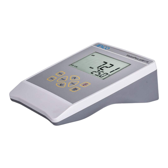
- Page 1 Operation Manual MODEL pH6175 Microcomputer Based pH/ORP/Temperature Benchtop Meter pH6175...
-
Page 2: Table Of Contents
CONTENTS GENERAL INTRODUCTION…………………....2 INITIAL INSPECTION……...………………....2 POWER INPUT…….……...………………......2 INSTALLING THE BATTERIES..…………....3 DISPLAY & KEYS FUNCTIONS…..……………..…...…..…3 ..............3 A. Display ................4 B. Keys OPERATIONAL PROCEDURES..……......5 .............5 A. Buffer Set Selection .............6 B. pH Calibration a. Calibration with an ATC/Temp probe in the pH-AUTOLOCK ................6 mode b. -
Page 3: General Introduction
INITIAL INSPECTION Carefully unpack the unit and accessories. Inspect for damages made in shipment. If any damage is found, notify your Jenco representative immediately. All packing materials should be saved until satisfactory operation is confirmed. POWER INPUT The model pH6175 can be powered by an 115V or 230VAC adaptor as well as 6 “AAA”... -
Page 4: Installing The Batteries
AC line voltage is correct. If the wrong AC adaptor is supplied, notify your Jenco representative immediately. INSTALLING THE BATTERIES To insert the batteries into the meter, follow the procedure outlined below. -
Page 5: Keys
1. WAIT- 7. AUTO This will be displayed when the AUTOLOCK mode indicator. unit is still waiting for a stable reading or end point sensing. 8. Buffer selection This indicator will flash if the 2. BAT- unit is not yet calibrated. This Low battery indicator. -
Page 6: Operational Procedures
Clear- It is used to clear the unit when error signal appears. It clears all calibration values stored in the internal memory. Under normal use the key will not be activated unless pressed and held for 2 seconds to prevent accidental lear erasing stored memory. -
Page 7: Ph Calibration
[Note: There is no need to repeat this procedure every time the unit is power up unless one decides to change the buffer settings.] B. pH Calibration The pH6175 uses one, two or three point calibration. [Note: If the unit uses two or three point calibration, the first point must be 6.86/7.00, and the second point can either be 4.00/4.01 or 9.18/ 10.01.] Calibration with an ATC/Temp probe in the pH-AUTOLOCK... -
Page 8: Calibration With Manual Temperature Compensation In The Ph Autolock Mode
[Note: At this moment, press the “Mode” key, the unit will exit the calibration mode. Dual point calibration is complete.] Rinse the pH and ATC/Temp probe in distilled water and immerse them in the third buffer solution (either 9.18/10.01 or 4.00/4.01). Allow temperature reading to stabilize, then press “Slope”... -
Page 9: Calibration With An Atc/Temp Probe In The Ph Non- Autolock Mode
Calibration with an ATC/Temp probe in the pH NON- AUTOLOCK mode. Turn the unit on. Press “Clear” key for 2 seconds, all LCD elements will lit up. The meter clears all calibration values stored in internal memory. Connect the pH electrode to the BNC connector and the ATC/Temp probe to the ATC/Temp connector of the unit: “ATC”... -
Page 10: Calibration With Manual Temperature Compensation In The Ph Non-Autolock Mode
key for about 5 seconds to display the new electrode efficiency. Calibration with manual temperature compensation in the pH NON-AUTOLOCK mode. Turn the unit on. Press “Clear” key for 2 seconds, all LCD elements will lit up. The meter clears all calibration values stored in internal memory. -
Page 11: Measurement With Manual Temperature Compensation In The Ph Autolock Mode
Press “Mode” key until “pH” icon and “AUTO” icon lit up. Rinse the pH electrode and ATC/temp probe with distilled water and immerse in the sample to be measured. Remove any air bubbles trapped around the probe by shaking or stirring the probe. -
Page 12: Measurement With Manual Temperature Compensation In The Ph Non-Autolock Mode
Measurement with manual temperature compensation in the pH NON-AUTOLOCK mode. Connect the pH electrode to the BNC connector of the unit. The “MAN” icon will lit up. Set unit to display the sample temperature by pressing the up and down keys(0.0 to 100.0℃). Repeat steps 2~4 of “Measurement with an ATC/Temp probe in the pH NON- AUTOLOCK mode”. -
Page 13: Ph Buffers
be measured. Allow sufficient time for the display to stabilize. The instrument will display the mV value of the sample. pH BUFFERS The temperature coefficient of pH calibration buffers 4.01, 6.86, 7.00,9.18 and 10.01 are stored inside the instrument. The buffers used to calibrate the instrument must exhibit the same temperature characteristics as the stored values. -
Page 14: Error Displays And Troubleshooting
3. Measured temperature is 3. Bring sample temperature out of the 0.0 to 100.0°C into the correct measuring range. range. [Note: If the meter still does not perform normally after the above measures are taken, call Jenco representative.]... -
Page 15: Specifications
SPECIFICATIONS Display Range Resolution Accuracy 0.00 to 14.00 pH 0.01 pH ±0.01 pH -1999.9 to 1999.9 mV 0.1mV ±0.4/±1 mV Temperature 0.0 to 100.0 °C 0.1 °C ±0.2°C pH 7.00, 4.01, 10.01 or pH pH buffer recognition 6.86, 4.00, 9.18 pH Temperature compensation AUTO/MAN 0.0°C to 100.0 °C pH Buffer Temperature range 0°C to 60.0°C... -
Page 16: Warranty
If you purchased the item from our Jenco distributors and it is under warranty, please contact them to notify us of the situation.
Need help?
Do you have a question about the VisionPlus pH6175 and is the answer not in the manual?
Questions and answers