
Related Manuals for Windsor SABER GLIDE 10053070


Summary of Contents for Windsor SABER GLIDE 10053070
- Page 1 SCRUBBER Operating Instructions (ENG) MODELS: SG28 SG32 SG36 SGW32 10052450 10052460 10052470 10053070 AFTER SN: 1000136404 IPX4 Read these instructions before using the machine 86037580 06/26/15 PRV NO. 980207...
-
Page 2: Machine Data Log/Overview
Warranty Registration Thank you for purchasing a Windsor product. Warranty registration is quick and easy. Your registration will allow us to serve you better over the lifetime of the product. -
Page 3: Table Of Contents
TABLE OF CONTENTS Service Schedule..........4-17 Machine Data Log/Overview........ 2 Machine Troubleshooting........4-18 Table of Contents ..........3 Serial Numbers ..........5-82 HOW TO USE THIS MANUAL How to use this Manual........1-1 SAFETY Important Safety Instructions ....... 2-1 Hazard Intensity Level. -
Page 4: Service Schedule
They are Parts may be ordered from authorized Windsor listed in this general order: dealers. When placing an order for parts, the machine model and machine serial number are Batteries important. -
Page 5: Important Safety Instructions
IMPORTANT SAFETY INSTRUCTIONS When using an battery powered appliance, basic precaution must always be followed, including the following: READ ALL INSTRUCTIONS BEFORE USING THIS MACHINE. WARNING: To reduce the risk of fire, electric shock, or injury: Use only indoors. Do not use outdoors or expose to rain. Use only as described in this manual. -
Page 6: Hazard Intensity Level
WHEN SERVICING MACHINE: Avoid moving parts. Do not wear loose clothing; jackets, shirts, or sleeves when working on the machine. Use Windsor approved replacement parts. WARNING Batteries emit hydrogen gas. Explosion or fire can result. Keep sparks and open flame away. Keep solution tank in raised position when charging. -
Page 7: Safety Label Location
SAFETY LABEL LOCATION NOTE: These drawings indicate the location of safety labels on the machine. If at any time the labels become illegible, promptly replace them. SAFETY DECAL 86252530 PRV NO. 81494 CIRCUIT BREAKER 86244130- 28 IN & 32 IN BATTERY CAUTION 86252520 PRV NO. -
Page 8: Technical Specifications
TECHNICAL SPECIFICATIONS ITEM DIMENSION/CAPACITY Nominal power 2.9 kW Rated Voltage 36 Volts DC Rated Amperage 80 amps (28in & 32in) 95 amps (36in) Batteries 6 x 6 Volt 250-335 AH @20 hr. rate Scrub Brush Motors 2 x 1.0 HP (746 W) 28in & 32in 3 x 1.0 HP (746 W) 36in Vacuum Motor(s) 1 x .75 HP (560 W) Standard, second motor... - Page 9 TECHNICAL SPECIFICATIONS ITEM MEASURE Height 1 51 inches (130 cm) Height 2 56.6 inches (144 cm) Length 63.5 inches (161 cm) Width without squeegee and scrub head 31 inches (79 cm) Width of squeegee 33 inches (84 cm) Width of scrub path for 28 in. (71 cm) 28 inches (71 cm) Width of scrub path for 32 in.
-
Page 10: How The Machine Works
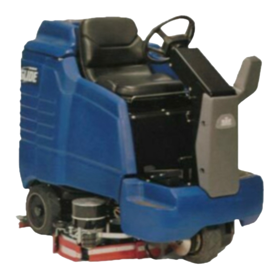
HOW THE MACHINE WORKS The Saber Glide is a battery powered, self- The 36 in. disk scrub system consists of three rotary propelled, hard floor scrubber intended for type disk scrub brushes, motors, scrub deck skirts, commercial use. The appliance applies a cleaning lift actuator, shift actuator and controls. -
Page 11: Components
COMPONENTS 8. Scrub head 1. Control panel 9. Scrub head side squeegee 2. Front cover 10. Solution tank drain hose 3. Side cover 11. Solution tank cover 4. Tank 12. Squeegee 5. Recovery tank cover 13. Vacuum motor 6. Recovery tank dome 7. -
Page 12: Controls
CONTROLS 86037580 GLIDE 01/03/07... - Page 13 CONTROLS 9. Recycle switch (optional) 1. Key switch 10. Recycle indicator light (optional) 2. Emergency stop button 11. Headlight switch (optional) 3. One touch switch 12. Brake pedal 4. Brush pressure switch 13. Parking brake lever 5. Solution control switch 14.
- Page 14 CONTROLS 3. ONE TOUCH SWITCH This switch controls the scrub brushes and vacuum all in one touch. To start scrubbing, press the one touch switch. The brush drive motors will turn on, the scrub deck will lower to the "light scrub" position, the solution will flow at “two bars” rate, the squeegee will lower and the vacuum will turn on.
- Page 15 CONTROLS 5. SOLUTION CONTROL SWITCH This switch controls the amount of solution flow to the scrub deck. There are 7 different flow settings. To increase the solution flow, press the solution control switch (+). To decrease solution flow, press the top of the switch (-).
- Page 16 CONTROLS 7. DISPLAY TOGGLE SWITCH The display toggle switch allows you to change the information display screen. Two screens are available. • INFORMATION DISPLAY –SCREEN 1 • INFORMATION DISPLAY –SCREEN 2 • The hour meter is viewed on screen 2 of the information display. Hours are displayed for key ON time, brush run time, and traction motor time.
- Page 17 CONTROLS • The float switch is located inside the recovery tank. The purpose of the float switch is to notify the user that the recovery tank is full. When the float switch is activated, the scrub brush motors and solution flow will stop, the scrub deck will raise, the squeegee will rise after 60 seconds, and the vacuum motor will turn off 10 seconds later.
- Page 18 CONTROLS 9. RECYCLE SWITCH (OPTIONAL) This switch controls the solution recycle pump. To start recycle pump, press the switch. A green light above the circuit breakers will indicate that pump is on. The solution control switch will control the speed of the pump and therefore the amount of solution flow to the scrub deck. Make sure there is an adequate amount of water in recovery tank before starting recycle pump, and turn off recycle pump when water level reaches filter.
- Page 19 CONTROLS 12. BRAKE PEDAL The brake pedal is located on the floor to the right side of the steering column pedestal. The pedal operates the disc brake on the drive wheel. To slow or stop the vehicle, apply pressure to the brake pedal. 13.
- Page 20 CONTROLS 15. STEERING WHEEL The steering wheel turns the front wheel causing the machine to change direction. 16. STEERING TILT LEVER The steering tilt lever is located on the right side of the steering wheel. To engage the tilt adjustment, pull on the lever and adjust the steering column to desired position.
-
Page 21: Machine Operation
MACHINE OPERATION PRE-RUN MACHINE INSPECTION 3. The solution tank can be filled to the FULL 1. Do a pre-run inspection to find possible marking of the fill inlet. Leave room for problems that could cause poor performance or detergent. The solution tank capacity is 30 lost time from breakdown. -
Page 22: Emergency Stop Procedures
MACHINE OPERATION TO BEGIN SCRUBBING EMERGENCY STOP PROCEDURE 1. Turn key switch to off position. If an electrical When operating the CAUTION machine around people, problem is suspected push in emergency stop pay close attention for unexpected movement. button. Use extra caution around children. 2. -
Page 23: Emptying & Cleaning Tanks
MACHINE OPERATION EMPTYING AND CLEANING TANKS SOLUTION TANK 1. Park the machine next to a floor drain. Drain RECOVERY TANK hose is on left rear adjacent to recovery tank 1. Touch the one-touch switch (#1) on the control drain hose. panel to raise the scrub deck, stop the motors, 2. -
Page 24: Maintenance
MAINTENANCE 1. Batteries Brake 2. Battery Tray Drain Hose 10. Steering Chain Tensioner 3. Squeegee Adjustment 11. Vacuum Motor 4. Side Squeegee Adjustment 12. Brush Motor 5. Scrub Brushes 13. Traction Motor 6. Vacuum Filter 14. Fuse 7. Float Switch 15. -
Page 25: Batteries
MAINTENANCE 1. BATTERIES 6. Ensure that all connections are tight and all The batteries provide the power to operate the corrosion removed. machine. The batteries require regular maintenance 7. Every 4 to 6 months, remove the batteries from to keep them operating at peak efficiency. the machine and clean the battery cases and To get the greatest life from the batteries charge battery compartment. - Page 26 MAINTENANCE TO CHARGE BATTERIES 8. Plug the charger into the battery connector. Plug battery charger into power outlet. The charger When servicing machine, WARNING gauge should indicate that the batteries are avoid contact with acid. charging. If the charger does not automatically start up, verify that charger is plugged into Batteries emit hydrogen WARNING...
-
Page 27: Battery Tray Drain Hose
MAINTENANCE TO REMOVE BATTERIES TO REPLACE BATTERIES 1. Stop the machine in a clean area next to the 1. Refer to diagram. Place batteries in battery charger. compartment. 2. Turn off machine and set parking brake. 2. Connect all jumper cables positive to negative to the six batteries. - Page 28 MAINTENANCE 3. SQUEEGEE ADJUSTMENT TO ADJUST SQUEEGEE DEFLECTION Adjusting the squeegee is a two-part process. First, the squeegee tool must have correct pitch in order for the squeegee blade to have the same deflection at each tip as well as the center. The pitch adjustment is facilitated by the use of a spirit level mounted on the squeegee tool.
- Page 29 MAINTENANCE TO REPLACE OR ROTATE REAR TO REPLACE OR ROTATE FRONT SQUEEGEE BLADES SQUEEGEE BLADES 1. With the squeegee in the up position, turn off the 1. With squeegee assembly on bench, loosen key switch and set the parking brake. retaining bolt and locking nut on the left side of the retaining strap.
-
Page 30: Squeegee
MAINTENANCE Right Side Squeegee and Secondary Side 4. SIDE SQUEEGEE ADJUSTMENT Squeegee Blade TO REPLACE OR ROTATE SIDE SQUEEGEE 1. Loosen the locking knob and unscrew it until BLADES (28 in. & 32 in.) it is near the top of the stud. Remove the side squeegee assembly. - Page 31 MAINTENANCE 5. SCRUB BRUSHES REPLACING OR INSTALLING SCRUB BRUSHES There are five different types of brushes available to The scrub brushes should be checked before each cover applications from cleaning heavily soiled floors days work for wire, string, wear, or damage. The to polishing.
-
Page 32: Brake
MAINTENANCE 3. Locate release lever on top of brush or pad SOLUTION STRAINER driver. With finger rotate release lever against The solution strainer is located behind the right rear spring pressure counter clockwise. Brush/pad wheel of the Glide. The solution strainer protects the driver will release and drop down. -
Page 33: Vacuum Motor
6. Remove vacuum motor from mounting bracket Note: assembly. Place 7. Reverse steps to install. stop in groove. Vacuum Motor Carbon Brushes Replacement (Windsor) End Cap Carbon Important: Brushes These brushes wear quicker as the length shortens due to increased heat. Spring inside brush housing will damage motor if brushes are allowed to wear away completely. -
Page 34: Brush Motor
MAINTENANCE BRUSH MOTOR CARBON BRUSH 12. BRUSH MOTOR REPLACEMENT (Refer to Brush Motor Group in parts section of manual). 1. Scribe alignment marks on motor barrel to motor WARNING cap and motor barrel to motor frame. Do not use a pressure washer to clean around 2. -
Page 35: Traction Motor
MAINTENANCE 13. TRACTION MOTOR 14. FUSE Do not use a pressure The fuse is a one-time circuit protection device WARNING washer to clean around the designed to stop the flow of electrical current in brush motors. Use tap pressure only. the event of an electrical overload. -
Page 36: Squeegee Actuator
MAINTENANCE 16. SQUEEGEE ACTUATOR SQUEEGEE ACTUATOR ADJUSTMENT REMOVAL/REPLACEMENT The actuator will need to be adjusted when replaced. The actuator needs to be set such that it FOR SAFETY: Before leaving or servicing does not bind against itself in the raised/retracted machine, stop on a level surface, turn off position, and does not bind against the axle in the machine and set parking brake. -
Page 37: Scrub Deck Actuator
MAINTENANCE 17. SCRUB DECK ACTUATOR SCRUB DECK ACTUATOR ADJUSTMENT REMOVAL/REPLACEMENT The actuator will need to be adjusted when replaced. The actuator needs to be set such that the scrub FOR SAFETY: Before leaving or servicing deck stops barely touch the rubber bumpers on the machine, stop on a level surface, turn off frame in the raised/retracted position. -
Page 38: Transporting Machine
TRANSPORTING MACHINE PREPARATION FOR TRANSPORTING TOWING OR PUSHING MACHINE Remove squeegee tool to eliminate interference with The machine may be towed for short distances at tie-downs. speeds not to exceed 5 mph. Be careful to avoid Scrub head must be in the up position before damaging machine. -
Page 39: Jacking Machine
JACKING MACHINE MACHINE JACKING MACHINE STORAGE The machine may be jacked up for service or If the machine is to be stored for extended periods of inspection by using the specified jack locations. time, the following steps must be taken to minimize Always block the tires when jacking up the machine. - Page 40 MAINTENANCE SERVICE SCHEDULE MAINTENANCE BEFORE EACH AFTER EACH WORK PERIOD WORK PERIOD Check water level of batteries after charging; add distilled water if necessary Check that recovery tank cover seals tightly Visually check for damaged or worn tires Check brushes or pads for proper installation Check vacuum hose connections Check that squeegee is securely attached and properly adjusted...
- Page 41 MACHINE TROUBLESHOOTING ERROR PROBLEM CAUSE SOLUTION CODE No power to machine Battery disconnected Check connections of all battery cable connections Emergency shut-off Reset activated Battery cables corroded Clean connections Main fuse blown Replace fuse Faulty key switch Replace switch Little or no propel Low battery charge Charge batteries Machine turned on with...
- Page 42 MACHINE TROUBLESHOOTING PROBLEM CAUSE ERROR SOLUTION CODE Vacuum motor does not run, Recovery tank full Drain recovery tank or runs slowly Recovery tank float Clean float switch switch dirty Loose motor connection 7700 Check motor wires and connections Worn vacuum motor Replace brushes, check brushes commutator...
- Page 43 MACHINE TROUBLESHOOTING - CONTROLLER FAULT CODES ERROR PROBLEM SOLUTION CODE None LCD display on, but incomplete Disconnect batteries and wait 1 minute before re-applying power. 0A01 Power down error Disconnect batteries and wait 1 minute before re-applying power. 0204 Memory corrupt Replace controller.
- Page 44 NOTES: 4-21 86037580 GLIDE 01/03/07...
- Page 45 Table of contents SABER GLIDE 28" RIDER SCRUBBER (ALL MODELS) 9010 BRAKE – FROM SERIAL NUMBER *(7) 9020 BRAKE – TO SERIAL NUMBER *(7) 9030 CIRCUIT BREAKER 9040 DECAL GROUP 9050 FRONT BUMPER & FLOOR 9060 FORWARD/REVERSE PEDAL 9070 SCRUB BRUSHPAD /DRIVER 28 IN. DISK 9080 SCRUB BRUSHPAD /DRIVER 32 IN.
- Page 46 Table of contents 9380 BACK-UP ALARM-OPTION 9390 DUAL VACUUM MOTOR-OPTION 9400 WARNING LIGHT-OPTION 9410 SERIAL NUMBER Valid on 05.10.2018 Page 2 / 97...
-
Page 47: Saber Glide 28" Rider Scrubber (All Models)
SABER GLIDE 28" RIDER SCRUBBER (ALL MODELS) Description Quantity Unit 9010 BRAKE – FROM SERIAL NUMBER *(7) 1.000 9020 BRAKE – TO SERIAL NUMBER *(7) 1.000 9030 CIRCUIT BREAKER 1.000 9040 DECAL GROUP 1.000 9050 FRONT BUMPER & FLOOR 1.000 9060 FORWARD/REVERSE PEDAL 1.000... - Page 48 SABER GLIDE 28" RIDER SCRUBBER (ALL MODELS) Description Quantity Unit 9340 WIRING-CONTROL PANEL 1.000 9350 WIRING-DRIVE MOTOR 1.000 9360 WIRING DIAGRAM 1.000 9370 ACCESSORY PUMP-OPTION 1.000 9380 BACK-UP ALARM-OPTION 1.000 9390 DUAL VACUUM MOTOR-OPTION 1.000 9400 WARNING LIGHT-OPTION 1.000 9410 SERIAL NUMBER 1.000 Valid on 05.10.2018...
-
Page 49: 9010 Brake - From Serial Number
9010 BRAKE – FROM SERIAL NUMBER *(7) Valid on 05.10.2018 Page 5 / 97... - Page 50 9010 BRAKE – FROM SERIAL NUMBER *(7) Article no. Description Quantity Unit 8.635-890.0 ROD, 5/16-24 ADJUSTMENT 1.000 8.635-886.0 ROD END, CLEVIS 5/16-24 2.000 8.635-879.0 ARM, BRAKE LEVER 1.000 8.635-560.0 PAD, BRAKE PEDAL 1.000 8.627-962.0 WASHER, .41 FLT PLTCNYL 2.000 8.627-894.0 WASHER, 1/4 STL ZNPLT 1.000 8.627-689.0...
-
Page 51: 9020 Brake - To Serial Number
9020 BRAKE – TO SERIAL NUMBER *(7) Valid on 05.10.2018 Page 7 / 97... - Page 52 9020 BRAKE – TO SERIAL NUMBER *(7) Article no. Description Quantity Unit 8.627-688.0 SCREW, 1/4-20 X .375 HHCS SS 1.000 8.627-894.0 WASHER, 1/4 STL ZNPLT 1.000 8.625-556.0 SPRING, .31X .04X 3.0EXT,CS,ZC 1.000 8.627-962.0 WASHER, .41 FLT PLTCNYL 2.000 8.635-560.0 PAD, BRAKE PEDAL 1.000 8.635-554.0 PEDAL, BRAKE SRS...
- Page 53 9020 BRAKE – TO SERIAL NUMBER *(7) Article no. Description Quantity Unit 8.627-128.0 Nut 4-40 HEXSTRW STL ZNPLT 2.000 Valid on 05.10.2018 Page 9 / 97...
-
Page 54: 9030 Circuit Breaker
9030 CIRCUIT BREAKER Valid on 05.10.2018 Page 10 / 97... - Page 55 9030 CIRCUIT BREAKER Article no. Description Quantity Unit Remark 8.627-399.0 SCREW, 6-32 X .375 PHPNHMS SS 6.000 4 PER 28 & 32/6 PER 36 8.627-930.0 WASHER, 6 SPL SS 6.000 4 PER 28 & 32/6 PER 36 8.600-192.0 BREAKER, 25A 50VDC CIRCUIT 3.000 2 PER 28 &...
-
Page 56: 9040 Decal Group
9040 DECAL GROUP Valid on 05.10.2018 Page 12 / 97... - Page 57 9040 DECAL GROUP Article no. Description Quantity Unit Remark 8.600-497.0 Label WINDSOR LOGO DOMED 1.000 8.624-351.0 Label CONTROL PANEL 1.000 8.624-357.0 LABEL GLIDE 2.000 8.624-350.0 LABEL, SRS CHARGING 1.000 8.624-414.0 LABEL, GLIDE 36 TRIO + CB 1.000 36 IN. 8.624-413.0 LABEL, GLIDE TRIO + CB 1.000...
-
Page 58: 9050 Front Bumper & Floor
9050 FRONT BUMPER & FLOOR Valid on 05.10.2018 Page 14 / 97... - Page 59 9050 FRONT BUMPER & FLOOR Article no. Description Quantity Unit 8.624-835.0 PAD, FLOOR 1.000 8.627-678.0 SCREW, 5/16-18 X .75 HHCS SS 2.000 8.601-067.0 WASHER, 5/16 FLT SS 7.000 8.627-691.0 SCREW, 5/16-18 X 3 HHCS SS NP 5.000 8.608-232.0 PLATE, FLOOR 1.000 8.603-182.0 COVER, FRONT BUMPER...
-
Page 60: 9060 Forward/Reverse Pedal
9060 FORWARD/REVERSE PEDAL Valid on 05.10.2018 Page 16 / 97... - Page 61 9060 FORWARD/REVERSE PEDAL Article no. Description Quantity Unit 8.600-581.0 NUT, 1/4-20 HEX NYLOCK SS 3.000 8.600-738.0 SPACER, .5 OD X .26 ID X 1.5L 1.000 8.607-831.0 PEDAL, SMALL RIDER 1.000 8.627-385.0 SCREW, 1/4-20 X 2 HHCS SS 1.000 8.627-694.0 SCREW, 1/4-20 X 3.5 HHCS SS NP 1.000 8.624-834.0 PAD, FWD/REV PEDAL...
-
Page 62: 9070 Scrub Brushpad /Driver 28 In. Disk
9070 SCRUB BRUSHPAD /DRIVER 28 IN. DISK Valid on 05.10.2018 Page 18 / 97... - Page 63 9070 SCRUB BRUSHPAD /DRIVER 28 IN. DISK Valid on 05.10.2018 Page 19 / 97...
- Page 64 9070 SCRUB BRUSHPAD /DRIVER 28 IN. DISK Valid on 05.10.2018 Page 20 / 97...
- Page 65 9070 SCRUB BRUSHPAD /DRIVER 28 IN. DISK Article no. Description Quantity Unit 8.600-025.0 PAD DRIVER, 14" SD 2.000 8.628-385.0 BRUSH, 14" SUPER AGGRESSIVE SD 2.000 8.600-028.0 Brush 14" MILD GRIT SD 2.000 8.600-027.0 Brush 14" NYLON SD 2.000 8.600-026.0 BRUSH, 14" POLYPROPYLENE SD 2.000 8.600-507.0 Lock PAD CENTER SNAP,TWO STEP...
-
Page 66: 9080 Scrub Brushpad /Driver 32 In. Disk
9080 SCRUB BRUSHPAD /DRIVER 32 IN. DISK Valid on 05.10.2018 Page 22 / 97... - Page 67 9080 SCRUB BRUSHPAD /DRIVER 32 IN. DISK Valid on 05.10.2018 Page 23 / 97...
- Page 68 9080 SCRUB BRUSHPAD /DRIVER 32 IN. DISK Article no. Description Quantity Unit 8.600-029.0 PAD DRIVER, 16" SD 2.000 8.600-034.0 Brush 16" SUPER AGGRESSIVE SD 2.000 8.600-033.0 Brush 16" MILD GRIT SD 2.000 8.600-031.0 Brush 16" NYLON SD 2.000 8.600-030.0 Brush 16" POLYPROPYLENE SD 2.000 8.600-507.0 Lock PAD CENTER SNAP,TWO STEP...
-
Page 69: 9090 Scrub Brushpad /Driver 36 In. Disk
9090 SCRUB BRUSHPAD /DRIVER 36 IN. DISK Valid on 05.10.2018 Page 25 / 97... - Page 70 9090 SCRUB BRUSHPAD /DRIVER 36 IN. DISK Valid on 05.10.2018 Page 26 / 97...
- Page 71 9090 SCRUB BRUSHPAD /DRIVER 36 IN. DISK Article no. Description Quantity Unit 8.600-017.0 PAD DRIVER, 12" SD 3.000 8.628-382.0 BRUSH, 12" SUPER AGGRESSIVE SD 3.000 8.616-807.0 MOTOR 3.000 8.600-020.0 Brush 12" MILD GRIT SD 3.000 8.600-018.0 Brush 12" POLYPROPYLENE SD 3.000 8.600-507.0 Lock PAD CENTER SNAP,TWO STEP...
-
Page 72: 9100 Scrub Deck-28 In Disk
9100 SCRUB DECK-28 IN DISK Valid on 05.10.2018 Page 28 / 97... - Page 73 9100 SCRUB DECK-28 IN DISK Article no. Description Quantity Unit Remark 8.613-682.0 SERVICE SLND SPRG KIT 1.000 SERVICE ONLY 8.600-346.0 Protection part SRVC PART SLND 1.000 SERVICE ONLY 8.600-525.0 Motor complete 36V 330 RPM GEAR 2.000 8.600-189.0 X-REF 140394 OBS 10/04 1.000 SERVICE ONLY 8.627-913.0...
- Page 74 9100 SCRUB DECK-28 IN DISK Article no. Description Quantity Unit Remark 8.627-692.0 SCREW, 3/8-16 X 1 HHCS SS NP 2.000 Valid on 05.10.2018 Page 30 / 97...
-
Page 75: 9110 Scrub Deck Side Squeegee-28 In Disk
9110 SCRUB DECK SIDE SQUEEGEE-28 IN DISK Valid on 05.10.2018 Page 31 / 97... - Page 76 9110 SCRUB DECK SIDE SQUEEGEE-28 IN DISK Article no. Description Quantity Unit 8.609-422.0 SKIRT, RIGHT 1.000 8.608-216.0 Plate right deck 1.000 8.622-683.0 Spring EXT .68D X3.00L X.098W 4.000 8.600-702.0 SCREW, 5/16-18 X 1.25 HHCS SS NP 6.000 8.601-067.0 WASHER, 5/16 FLT SS 10.000 8.609-423.0 SKIRT, LEFT...
-
Page 77: 9120 Scrub Deck Lift-28 In & 32 In
9120 SCRUB DECK LIFT-28 IN & 32 IN Valid on 05.10.2018 Page 33 / 97... - Page 78 9120 SCRUB DECK LIFT-28 IN & 32 IN Article no. Description Quantity Unit Serial number from 8.627-260.0 PIN, COTTER HAIR .148 X 2.69L STL ZNPLT 1.000 *(2) 8.635-295.0 ACTUATOR, 36VDC, 2.0 STROKE 1.000 *(6) 8.600-867.0 Cotter 3/8" RING 4.000 8.609-225.0 Deck Lift Asm.
-
Page 79: 9130 Scrub Deck -32 In
9130 SCRUB DECK -32 IN Valid on 05.10.2018 Page 35 / 97... - Page 80 9130 SCRUB DECK -32 IN Article no. Description Quantity Unit 8.613-682.0 SERVICE SLND SPRG KIT 1.000 8.600-346.0 Protection part SRVC PART SLND 1.000 8.600-525.0 Motor complete 36V 330 RPM GEAR 2.000 8.600-189.0 X-REF 140394 OBS 10/04 1.000 8.627-381.0 SCREW, 1/4-20 X 1 HHCS SS 2.000 8.608-795.0 STRAP, 32 IN REAR SQUEEGEE...
-
Page 81: 9140 Scrub Deck Side Squeegee -32 In
9140 SCRUB DECK SIDE SQUEEGEE –32 IN Valid on 05.10.2018 Page 37 / 97... - Page 82 9140 SCRUB DECK SIDE SQUEEGEE –32 IN Article no. Description Quantity Unit 8.609-422.0 SKIRT, RIGHT 1.000 8.608-684.0 SCRUB DECK 32 SIDE SQUEEGEE 1.000 8.622-683.0 Spring EXT .68D X3.00L X.098W 4.000 8.600-702.0 SCREW, 5/16-18 X 1.25 HHCS SS NP 6.000 8.601-067.0 WASHER, 5/16 FLT SS 10.000 8.609-423.0...
-
Page 83: 9150 Scrub Deck-36 In Main
9150 SCRUB DECK-36 IN MAIN Valid on 05.10.2018 Page 39 / 97... - Page 84 9150 SCRUB DECK-36 IN MAIN Article no. Description Quantity Unit 8.627-691.0 SCREW, 5/16-18 X 3 HHCS SS NP 1.000 8.600-155.0 HOSEBARB, 3/8MPT X3/8 90D 2.000 8.627-396.0 SCREW, 1/4-20 X 3 HHCS SS 1.000 8.600-084.0 ACTUATOR ASM, SRS 1.000 8.600-525.0 Motor complete 36V 330 RPM GEAR 2.000 8.600-189.0 X-REF 140394 OBS 10/04...
- Page 85 9150 SCRUB DECK-36 IN MAIN Article no. Description Quantity Unit 8.608-728.0 SPACER, PLATE 1.000 8.600-865.0 PIN, COTTER RING 1/4 X .041 X .844 1.000 8.608-729.0 SPACER, .5 OD X .334ID X .86OL 4.000 8.608-257.0 PLATE, ACTUATOR RETAINER 2.000 8.607-030.0 BRKT, ACTUATOR RETAINER 1.000 8.627-678.0 SCREW, 5/16-18 X .75 HHCS SS...
-
Page 86: 9160 Scrub Deck-36 In Retractable
9160 SCRUB DECK-36 IN RETRACTABLE Valid on 05.10.2018 Page 42 / 97... - Page 87 9160 SCRUB DECK-36 IN RETRACTABLE Article no. Description Quantity Unit 8.600-189.0 X-REF 140394 OBS 10/04 1.000 8.600-525.0 Motor complete 36V 330 RPM GEAR 1.000 8.600-955.0 BEARING, 15 X 35 X 11MM BALL 2RS SS 4.000 8.609-302.0 LINKAGE, SWING 2.000 8.600-952.0 Shaft DRIVER CYL.
- Page 88 9160 SCRUB DECK-36 IN RETRACTABLE Article no. Description Quantity Unit 8.627-647.0 SCREW, 3/8-16 X 2.25 HHCS SS 1.000 Valid on 05.10.2018 Page 44 / 97...
-
Page 89: 9170 Scrub Deck Side Squeegee-36 In
9170 SCRUB DECK SIDE SQUEEGEE-36 IN Valid on 05.10.2018 Page 45 / 97... - Page 90 9170 SCRUB DECK SIDE SQUEEGEE-36 IN Article no. Description Quantity Unit 8.600-563.0 NUT, 3/8-16 HEXTHIN NYLOCK SS 2.000 8.601-089.0 Wheel BUMPER 1.000 8.627-401.0 SCREW, 3/8-16 X 2 HHCS SS 1.000 8.600-581.0 NUT, 1/4-20 HEX NYLOCK SS 9.000 8.608-786.0 STRAP, SECONDARY SQUEEGEE 1.000 8.627-678.0 SCREW, 5/16-18 X .75 HHCS SS...
-
Page 91: 9180 Scrub Deck Lift-36 In
9180 SCRUB DECK LIFT-36 IN Valid on 05.10.2018 Page 47 / 97... - Page 92 9180 SCRUB DECK LIFT-36 IN Article no. Description Quantity Unit Serial number from Remark 8.600-346.0 Protection part SRVC PART SLND 1.000 SERVICE ONLY 8.600-462.0 KIT,SABER/STRIDE SQUEEGEE LIFT 1.000 SERVICE ONLY 8.600-872.0 PIN, CLEVIS 3/8 X 2.375 STL ZNPLT 1.000 8.601-449.0 ACTUATOR, 36VDC 3.5 STRK SG36 1.000 *(3)
- Page 93 9180 SCRUB DECK LIFT-36 IN Article no. Description Quantity Unit Serial number from Remark 8.623-315.0 CLAMP, 3/8 HOSE (D-SLOT) 1.000 8.628-206.0 HOSE, 1/2 ID NYLOBRD X 21.5 1.000 8.601-073.0 WASHER, 5/8 X .64 X 1.188 SS 2.000 Valid on 05.10.2018 Page 49 / 97...
-
Page 94: 9190 Seat & Side Cover
9190 SEAT & SIDE COVER Valid on 05.10.2018 Page 50 / 97... - Page 95 9190 SEAT & SIDE COVER Article no. Description Quantity Unit 8.625-315.0 SEAT, SUPER SUBURBAN BLK VINYL 1.000 8.625-707.0 Switch SEAT 1.000 8.622-374.0 SCREW, 1/4-20 X .59 PHPNHMS SS 2.000 8.627-689.0 SCREW, 5/16-18 X .75 PHTRHMS SS 6.000 8.627-678.0 SCREW, 5/16-18 X .75 HHCS SS 2.000 8.627-124.0 NUT, 1/4 PAL STL ZNPLT...
-
Page 96: 9200 Solution Delivery
9200 SOLUTION DELIVERY Valid on 05.10.2018 Page 52 / 97... - Page 97 9200 SOLUTION DELIVERY Article no. Description Quantity Unit Remark 8.627-378.0 SCREW, 1/4-20 X .75 HHCS SS NP 1.000 8.619-805.0 TEE, 3/4 FPT 1.000 8.607-682.0 HOSEBARB, SOLUTION HOSE MTG 1.000 8.600-581.0 NUT, 1/4-20 HEX NYLOCK SS 1.000 8.628-215.0 Hose 1IDX12WCLRX28" 1.000 8.623-618.0 FITTING, 3/4"...
-
Page 98: 9210 Squeegee - 28 In & 36 In
9210 SQUEEGEE – 28 IN & 36 IN Valid on 05.10.2018 Page 54 / 97... - Page 99 9210 SQUEEGEE – 28 IN & 36 IN Article no. Description Quantity Unit Remark 8.608-250.0 PLATE, SQUEEGEE TOP 32 IN 1.000 8.608-251.0 PLATE, SQG VERTICAL FILLER (F) 1.000 8.608-252.0 PLATE, SQG VERTICAL FILLER(R) 1.000 8.608-253.0 Plate SQUEEGEE BOTTOM 32 IN 1.000 8.627-413.0 SCREW, 8-32 X .375 PHPNHTC...
- Page 100 9210 SQUEEGEE – 28 IN & 36 IN Article no. Description Quantity Unit Remark 8.600-627.0 PIN, CLEVIS 5/16 X 1.625 STL ZNPLT 2.000 8.600-866.0 Cotter 5/16" RING 2.000 8.627-182.0 NUT, 5/16-18 X .028-.056PR CAGE 3.000 8.600-704.0 SCREW, 5/16-18 X 1 THUMB SS 3.000 8.600-149.0 BLADE, SQUEEGEE FRONT...
-
Page 101: 9220 Squeegee- 32 In
9220 SQUEEGEE- 32 IN Valid on 05.10.2018 Page 57 / 97... - Page 102 9220 SQUEEGEE- 32 IN Article no. Description Quantity Unit 8.635-170.0 PLATE, SQUEEGEE BOTTOM 1.000 8.635-168.0 PLATE ASM, SQUEEGEE TOP 37" 1.000 8.635-163.0 BAND, FRONT SQUEEGEE 1.000 8.635-156.0 PLATE, SQU. VERT. FILL. 32" R 1.000 8.635-155.0 PLATE, SQU. VERT, FILL. 32" 1.000 8.627-700.0 SCREW, 1/4-20 X 1.5 CARR SS...
- Page 103 9220 SQUEEGEE- 32 IN Article no. Description Quantity Unit 8.600-581.0 NUT, 1/4-20 HEX NYLOCK SS 2.000 8.600-565.0 NUT, 5/16-18 HEX STL ZNPLT 2.000 8.600-563.0 NUT, 3/8-16 HEXTHIN NYLOCK SS 4.000 8.600-489.0 KNOB,ALUM 3/8-16 NYLOCK NUT SS 2.000 8.600-135.0 BUSHING, SPANNER .435 X 1.10 4.000 Valid on 05.10.2018 Page 59 / 97...
-
Page 104: 9230 Squeegee Lift
9230 SQUEEGEE LIFT Valid on 05.10.2018 Page 60 / 97... - Page 105 9230 SQUEEGEE LIFT Article no. Description Quantity Unit Serial number from 8.627-786.0 SCREW, 3/8-16 X 3.75 HHCS SS 1.000 8.601-077.0 WASHER, 7/16 X1 X .08 FLT SS 3.000 8.601-016.0 Spring .62X.09X1.6 CS,ZC,GRND 1.000 8.600-887.0 BUSHING, 3/8 X .688 FLG 4.000 8.600-886.0 PIN, CLEVIS 3/8 X 5.5 STL ZNPLT 2.000...
-
Page 106: 9240 Steering-Upper
9240 STEERING-UPPER Valid on 05.10.2018 Page 62 / 97... - Page 107 9240 STEERING-UPPER Article no. Description Quantity Unit Remark 8.623-481.0 COVER, STEERING WHEEL 1.000 8.627-161.0 NUT, 5/8-18 HEXTHIN NYLOCK STL GR2 ZNPLT 1.000 8.625-961.0 Wheel STEERING 40 SPLINE HUB 1.000 8.625-323.0 SHAFT, UPPER STEERING 1.000 8.622-879.0 BUSHING, .753 X .875 X .75 FLG 2.000 8.609-220.0 COLUMN, 36 UPPER STEERING...
-
Page 108: 9250 Steering- Lower
9250 STEERING- LOWER Valid on 05.10.2018 Page 64 / 97... - Page 109 9250 STEERING- LOWER Article no. Description Quantity Unit 8.627-697.0 SCREW, 3/8-16 X .75 HHCS SS 1.000 8.625-833.0 UNIVERSAL JOINT, DOUBLE 1.000 8.623-280.0 CHAIN, #40, 1/2 PITCH X 36 1.000 8.608-231.0 PLATE, STEERING 1.000 8.608-284.0 PLATE, CHAIN TENSIONER 1.000 8.628-841.0 SCREW, M10-1.5 X 35 HH 1.000 8.600-581.0 NUT, 1/4-20 HEX NYLOCK SS...
-
Page 110: 9260 Tank
9260 TANK Valid on 05.10.2018 Page 66 / 97... - Page 111 9260 TANK Article no. Description Quantity Unit 8.623-343.0 Clamp worm gearing 2.50 4.000 8.603-327.0 TUBE ASM, VAC 1.000 8.627-660.0 SCREW, 10-12 X .75 PHTRHSMS SS TYPEA 2.000 8.606-631.0 BAFFLE, SMALL RIDER 1.000 8.627-395.0 SCREW, 6-32 X .5 PHPNHMS SS 1.000 8.623-479.0 COVER, CLP SOLUTION 1.000...
-
Page 112: 9270 Tank Cover
9270 TANK COVER Valid on 05.10.2018 Page 68 / 97... - Page 113 9270 TANK COVER Article no. Description Quantity Unit Serial number from 8.627-395.0 SCREW, 6-32 X .5 PHPNHMS SS 1.000 8.624-608.0 LANYARD, 18.0 W/LOOP & EYE 1.000 8.627-092.0 NUT, 6-32 HEX NYLOCK SS 1.000 8.627-691.0 SCREW, 5/16-18 X 3 HHCS SS NP 2.000 8.627-963.0 WASHER, 5/16 X 1.13 X .09 FLT...
-
Page 114: 9280 Vacuum
9280 VACUUM Valid on 05.10.2018 Page 70 / 97... - Page 115 9280 VACUUM Article no. Description Quantity Unit Remark 8.613-531.0 X-REF 8.683-043.0 5/09 1.000 SERVICE ONLY 8.623-080.0 BRUSH SET, 36V 3ST VAC AMETEK 1.000 SERVICE ONLY 8.627-480.0 SCREW, 1/4-20 X 1.5 HHMS STL GR5 ZNPLT 3.000 8.606-956.0 BRKT, VACUUM MOUNTING 1.000 8.600-301.0 Collar HOSE 1.5"...
-
Page 116: 9290 Wheel & Frame
9290 WHEEL & FRAME Valid on 05.10.2018 Page 72 / 97... - Page 117 9290 WHEEL & FRAME Article no. Description Quantity Unit Serial number from Remark 8.621-799.0 FRM, ASM STRNG MNT FOR 29256 1.000 SERVICE ONLY 8.622-219.0 MOTOR & GEARBOX FOR 29256 1.000 SERVICE ONLY 8.600-146.0 X-REF 14404 10/05 1.000 SERVICE ONLY 8.621-519.0 Bearing 60ID X 95OD 1.000 SERVICE ONLY...
-
Page 118: 9300 Wheel Motor -Service Parts
9300 WHEEL MOTOR –SERVICE PARTS Valid on 05.10.2018 Page 74 / 97... - Page 119 9300 WHEEL MOTOR –SERVICE PARTS Article no. Description Quantity Unit Serial number from 8.636-697.0 BAND BRAKE KIT, 8.635-895.0 1.000 *(7) 8.636-696.0 WHEEL, RED POLY 300 X 90 1.000 *(7) 8.636-698.0 BRUSH CAP AND O-RING KIT, 8.653-895.0 1.000 *(7) 8.636-695.0 BRUSH KIT, 8.635-895.0 1.000 *(7) Valid on 05.10.2018...
-
Page 120: 9310 Wiring-Battery
9310 WIRING-BATTERY Valid on 05.10.2018 Page 76 / 97... - Page 121 9310 WIRING-BATTERY Article no. Description Quantity Unit Remark 8.600-892.0 BOOT, RUBBER TERM. ISOLATOR 14.000 8.623-204.0 CABLE, 4GA BLACK X 78.5" 1.000 8.600-879.0 Fuse 125 AMP 1.000 8.600-685.0 SCREW, 1/4-20 X 1.25 SCHSET CP SS 2.000 8.625-591.0 STANDOFF, 1/4-20 X 1.0 HEX INS 2.000 8.627-913.0 WASHER, 5/16 SPLT STL ZNPLT...
-
Page 122: 9320 Wiring-Main Harness
9320 WIRING-MAIN HARNESS Valid on 05.10.2018 Page 78 / 97... - Page 123 9320 WIRING-MAIN HARNESS Article no. Description Quantity Unit 8.623-950.0 HARNESS, GLIDE TRIO + 1.000 8.623-339.0 CLAMP, 7/8 DIA "P~CUSHIONED 2.000 8.623-378.0 CONNECTOR, DT06-2S-CO15 2.000 8.600-581.0 NUT, 1/4-20 HEX NYLOCK SS 2.000 8.626-492.0 CABLE TIE, 7" UL/CSA 2.000 8.623-951.0 HARNESS GLIDE LCD 1.000 Valid on 05.10.2018 Page 79 / 97...
-
Page 124: 9330 Wiring - Main Harness Connection
9330 WIRING - MAIN HARNESS CONNECTION Valid on 05.10.2018 Page 80 / 97... - Page 125 9330 WIRING - MAIN HARNESS CONNECTION Article no. Description Quantity Unit 8.623-950.0 HARNESS, GLIDE TRIO + 1.000 8.626-729.0 WIRE, 14" GRN/18 76008 X 76011 1.000 8.623-031.0 BRKT, SW-PRO VALVE 1.000 8.623-204.0 CABLE, 4GA BLACK X 78.5" 1.000 8.623-901.0 HARNESS, SQUEEZE PLAY 1.000 8.623-951.0 HARNESS GLIDE LCD...
-
Page 126: 9340 Wiring-Control Panel
9340 WIRING-CONTROL PANEL Valid on 05.10.2018 Page 82 / 97... - Page 127 9340 WIRING-CONTROL PANEL Article no. Description Quantity Unit 8.623-949.0 HARNESS, CONTROL SMALL RIDER 1.000 8.623-951.0 HARNESS GLIDE LCD 1.000 8.623-950.0 HARNESS, GLIDE TRIO + 1.000 Valid on 05.10.2018 Page 83 / 97...
-
Page 128: 9350 Wiring-Drive Motor
9350 WIRING-DRIVE MOTOR Valid on 05.10.2018 Page 84 / 97... - Page 129 9350 WIRING-DRIVE MOTOR Article no. Description Quantity Unit 8.601-087.0 HARNESS, GLIDE PROPEL 1.000 Valid on 05.10.2018 Page 85 / 97...
-
Page 130: 9360 Wiring Diagram
9360 WIRING DIAGRAM Valid on 05.10.2018 Page 86 / 97... - Page 131 9360 WIRING DIAGRAM Article no. Description Quantity Unit 8.600-879.0 Fuse 125 AMP 1.000 8.600-187.0 BLADE, SQUEEGEE FRONT 1.000 8.600-144.0 Blade srcaper rear 1.000 8.600-369.0 Filter VAC 1.000 8.600-742.0 Stripper blade lateral LINATEX 1.000 8.600-758.0 Stripper blade lateral 32 1.000 8.600-739.0 SQUEEGEE, SIDE BLADE LINATEX 1.000 8.600-755.0...
-
Page 132: 9370 Accessory Pump-Option
9370 ACCESSORY PUMP-OPTION Valid on 05.10.2018 Page 88 / 97... - Page 133 9370 ACCESSORY PUMP-OPTION Article no. Description Quantity Unit 8.628-217.0 HOSE, 1\2 NYLOBRD X 26 1.000 8.623-315.0 CLAMP, 3/8 HOSE (D-SLOT) 6.000 8.619-755.0 Hosebarb 1/4MPT X 3/8 DL 1.000 8.608-182.0 PLATE, ACCESORY BULKHEAD 1.000 8.600-558.0 Nipple 1/4 FPT QD 1.000 8.624-041.0 HOSEBARB, 1/2 TEE 1.000 8.627-381.0...
- Page 134 9380 BACK-UP ALARM-OPTION Valid on 05.10.2018 Page 90 / 97...
- Page 135 9380 BACK-UP ALARM-OPTION Article no. Description Quantity Unit 8.600-572.0 NUT, 8-32 HEXSTRW LK STL ZNPLT 2.000 8.600-581.0 NUT, 1/4-20 HEX NYLOCK SS 2.000 8.627-375.0 SCREW, 1/4-20 X .625 HHCS SS NP 2.000 8.622-726.0 ALARM, BACK UP 1.000 8.601-063.0 WASHER, 1/4 SS 2.000 Valid on 05.10.2018 Page 91 / 97...
- Page 136 9390 DUAL VACUUM MOTOR-OPTION Valid on 05.10.2018 Page 92 / 97...
- Page 137 9390 DUAL VACUUM MOTOR-OPTION Article no. Description Quantity Unit Remark 8.623-080.0 BRUSH SET, 36V 3ST VAC AMETEK 1.000 SERVICE ONLY 8.613-531.0 X-REF 8.683-043.0 5/09 1.000 SERVICE ONLY 8.623-314.0 CLAMP, 2.0" WORM GEAR 4.000 8.607-684.0 HOSEBARB, 1.5 TEE, MACHINED 1.000 8.600-437.0 Hose assembly 1.5 BLK VAC X 21 1.000 8.600-777.0...
- Page 138 9400 WARNING LIGHT-OPTION Valid on 05.10.2018 Page 94 / 97...
- Page 139 9400 WARNING LIGHT-OPTION Article no. Description Quantity Unit 8.602-599.0 LIGHT ASM, FLASHING, 36V AMBER 1.000 8.627-660.0 SCREW, 10-12 X .75 PHTRHSMS SS TYPEA 3.000 8.626-495.0 CABLE TIE, .19W X 11.5L BLK 5.000 8.627-573.0 SCREW, 1/4-14 X .75 HWH STL ZNPLT 3.000 8.606-997.0 BRKT, LIGHT MOUNT...
- Page 140 9410 SERIAL NUMBER Valid on 05.10.2018 Page 96 / 97...
Need help?
Do you have a question about the SABER GLIDE 10053070 and is the answer not in the manual?
Questions and answers