Table of Contents
Advertisement
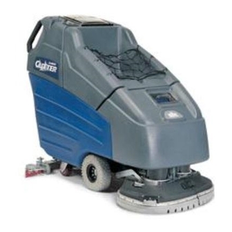
Walk Behind Scrubber
86039070-CD
07/06/15
Operating instructions (ENG)
MODELS:
Prior to Serial Number:
10052210000704
10052250000224
10052870000076
10052830000001
Or call Manufacturer.
Read these instructions before using the machine.
SC264
10052210
SCC264
10052250
BSCSC264
10052870
SCN264
10052830
IPX4
Advertisement
Table of Contents

Related Manuals for Windsor Saber Cutter SC264


Summary of Contents for Windsor Saber Cutter SC264
- Page 1 Walk Behind Scrubber Operating instructions (ENG) MODELS: SC264 10052210 SCC264 10052250 BSCSC264 10052870 SCN264 10052830 Prior to Serial Number: 10052210000704 10052250000224 10052870000076 10052830000001 Or call Manufacturer. IPX4 Read these instructions before using the machine. 86039070-CD 07/06/15...
-
Page 2: Machine Data Label
Warranty Registration Thank you for purchasing a Windsor product. Warranty registration is quick and easy. Your registration will allow us to serve you better over the lifetime of the product. To register you product go to : www.windsorind.com/WarrantyRegistration.aspx... -
Page 3: Table Of Contents
Table of Contents Machine Data Label ......2 Decal ........42 Overview . -
Page 4: How To Use This Manual
How To Use This Manual This manual contains the following sections: The SAFETY section contains important information regarding hazardous or unsafe practices of the • How to Use This Manual machine. Levels of hazards are identified that could • Safety result in product damage, personal injury, or severe •... -
Page 5: Safety
Safety Important Safety Instructions When using an battery powered appliance, basic precaution must always be followed, including the following: READ ALL INSTRUCTIONS BEFORE USING THIS MACHINE. To reduce the risk of fire, electric shock, or injury: Use only indoors. Do not use outdoors or expose to rain. Use only as described in this manual. -
Page 6: Hazard Intensity Level
WHEN SERVICING MACHINE: Avoid moving parts. Do not wear loose clothing; jackets, shirts, or sleeves when working on the machine. Use Windsor approved replacement parts. Batteries emit hydrogen gas. Explosion or fire can result. Keep sparks and open flame away. Keep top cover in raised position when charging. -
Page 7: Safety Label Location
Safety Safety Label Location NOTE: These drawings indicate the location of safety labels on the machine. If at any time the labels become illegible, promptly replace them. 86039070 CUTTER 24V... -
Page 8: Operations
Operations Technical Specifications ITEM DIMENSION/CAPACITY Nominal power 1450 W Rated Voltage 24VDC Rated Amperage 60 Amps Batteries 4 X 6 Volt 250-305-335 AH @ 20 hr rate Scrub Brush Motors 2 X .75 hp (0.56 kW) Vacuum Motor .75 hp (0.56 Kw) Propelling Motor .3 hp (0.22 Kw) Mass (GVW) - Page 9 Operations Technical Specifications ITEM MEASURE Height 45 in. (114 cm) Length with 26 in. (66 cm) scrub head 64 in. (163 cm) Width without squeegee and scrub head 24 in. (61 cm) Width of squeegee for 26 in. (66 cm) scrub head 35 in.
-
Page 10: How The Machine Works
Operations How The Machine Works The function of the recovery system is to vacuum the soiled water back into the recovery tank. The recovery The Saber Cutter is a battery powered, self-propelled, system consists of the squeegee, vacuum motor, float hard floor scrubber intended for commercial use. -
Page 11: Components
Operations Components 1. Control Panel 2. Front Cover 3. Recovery Tank 4. Recovery Tank Drain Hose 5. Scrub Head Shrouds 6. Solution Tank 7. Solution Tank Cover 8. Solution Tank Drain Hose 9. Solution Strainer 10. Squeegee 11. Aqua-Mizer 12. Top Cover 13. -
Page 12: Controls
Operations Controls 86039070 CUTTER 24V... - Page 13 Operations 1. Key Switch 3. SPEED CONTROL KNOB 2. Emergency Shut Off Switch (Optional) Controls the speed of the machine. 3. Speed Control Knob To increase speed, rotate knob clockwise. 4. Propel Control Lever To decrease speed, rotate knob counterclockwise. 5.
- Page 14 Operations 7. BRUSH PRESSURE LEVER 10. SQUEEGEE LIFT LEVER Adjusts the amount of brush pressure to the floor by Raises and lowers the squeegee. raising or lowering the scrub deck. To lower the squeegee, lift the lever from its raised To apply brush pressure, lower brush pressure lever to position.
- Page 15 Operations 13. BATTERY CHARGE LEVEL INDICATOR Indicates the charge level of the batteries. The meter display is divided into 10 vertical bars. Bar illuminated on the far right indicate full charge. Bars flashing near the left side indicate the batteries should be recharged.
-
Page 16: Machine Operation
Operations Machine Operation Filling Solution Tank FOR SAFETY: Before leaving or servicing Pre-Run Machine Inspection machine; stop on level surface, turn off machine and remove key. Do a pre-run inspection to find possible problems that could cause poor performance or lost time from break- 1. -
Page 17: Normal Scrubbing
Operations Normal Scrubbing To Begin Scrubbing Plan the scrubbing pattern in advance. The longest track is around the perimeter of the area to be cleaned. For efficient operation, the runs should be the longest When operating the machine around people, pay possible without turning, stopping, or raising and close attention for unexpected movement. -
Page 18: Emptying And Cleaning Tanks
Operations Double Scrub Recovery Tank For floors which are heavily soiled or have thick accu- 1. Unhook the large drain hose from the retainer. mulations of floor finish may not clean sufficiently with Unscrew the T-handle on plug enough to loosen one pass. -
Page 19: Maintenance
Maintenance Service Schedule MAINTENANCE DAILY WEEKLY MONTHLY 100 HRS 200 HRS Check batteries after charging; add water if necessary Check pad wear to prevent buildup of chemicals Check linkages and connectors for wear and damage Check hoses for wear, blockages, or damage Clean squeegee;... - Page 20 Maintenance 1. Batteries 2. Squeegee 3. Aqua Mizer 4. Scrub Brushes 5. Recovery Tank Float Shut-Off 6. Solution Strainer 7. Brush Motor 8. Traction Motor 9. Circuit Breakers 10. Brush Shroud & Brush Skirts 11. Vacuum Motor 86039070 CUTTER 24V...
-
Page 21: Batteries
Maintenance Batteries The batteries provide the power to operate the When servicing machine, avoid contact with machine. The batteries require regular maintenance to battery acid. keep them operating at peak efficiency. The machine batteries will hold their charge for long periods of time, but they can only be charged a certain Batteries emit hydrogen gas. -
Page 22: To Charge The Batteries
Maintenance Checking Battery Specific Gravity To Charge the Batteries Use a hydrometer to check the battery specific gravity. When servicing machine, avoid contact with battery acid. Batteries emit hydrogen gas. Explosion or fire can result. Keep sparks and open flame away. Keep covers open when charging. -
Page 23: Changing Batteries
Maintenance 5. Replace the battery caps, and leave them in place Changing Batteries while charging. Stop the machine in a clean area next to the charger. 6. Unplug the battery connector from the machine. Turn off machine. FOR SAFETY: When charging, connect the FOR SAFETY: Before leaving or servicing the charger to the batteries before connecting the machine;... -
Page 24: Squeegee Blades
Maintenance Squeegee Blades To Remove Squeegee Assembly The front squeegee blade allows solution to pass 1. With the squeegee in the up position, turn key through channels in the blade into the squeegee switch "OFF". assembly while maintaining vacuum to provide lift. The 2. -
Page 25: To Adjust Squeegee Pitch
Maintenance To Adjust Squeegee Pitch To Adjust Amount of Rear Squeegee Deflection 1. Choose a smooth, level surface. Turn "ON" the key switch. Lower the squeegee and drive forward 1. Choose a smooth, level surface. Lower the at least 2 feet (60cm.). squeegee and drive forward at least 2 feet (60cm). -
Page 26: Scrub Brushes
Maintenance Scrub Brushes Replacing or Installing Scrub Brushes There are four different types of brushes available to 1. With the scrub deck up, turn "OFF" the machine. cover applications from cleaning heavily soiled floors to FOR SAFETY: Before leaving or servicing the polishing. -
Page 27: Solution Strainer
Maintenance Solution Strainer Brush Motor Carbon Brush Replacement The solution strainer is located in front of the left front 1. Scribe alignment mark on motor barrel to motor wheel. The solution strainer protects the solenoid valve cap. Remove two bolts. from debris. -
Page 28: Traction Motor
Maintenance Traction Motor Circuit Breakers Circuit breakers interrupt the flow of power in the event of an electrical overload. When a circuit breaker is tripped, reset it by pressing the exposed button. If a Do not use a pressure washer to clean around the circuit breaker continues to trip, the cause of the elec- motors. -
Page 29: Vacuum Motor
7. Reverse steps to install. groove. Important: Vacuum Motor Carbon Brushes Replacement (Windsor) These brushes wear quicker as the length shortens End Cap due to increased heat. Spring inside brush housing will damage motor if brushes are allowed to wear Carbon away completely. -
Page 30: Greasing Axle
Maintenance Greasing Axle RECOMMENDED GREASING: 1-2 strokes of Mobiltemp®78 or compatible clay-based or calcium-based grease. 86039070 CUTTER 24V... -
Page 31: Machine Troubleshooting
Maintenance Machine Troubleshooting PROBLEM CAUSE SOLUTION Poor or no water pick-up Squeegee out of adjustment Adjust squeegee Debris caught on squeegee Remove debris Worn squeegee blades Rotate or replace squeegee blades Vacuum hose clogged Clear obstruction from hose Vacuum hose disconnected from Reconnect vacuum hose squeegee or recovery tank Vacuum hose damaged... - Page 32 Maintenance Machine Troubleshooting PROBLEM CAUSE SOLUTION Little or no solution flow to the Solution tank empty Fill solution tank floor Solution flow turned off or set too low Turn on or increase flow setting Solution strainer plugged Clean solution strainer Solution hoses obstructed Clear obstruction from hose Solution solenoid valve obstructed or...
- Page 33 Notes: 86039070 CUTTER 24V...
- Page 34 Notes: 86039070 CUTTER 24V...
-
Page 35: Parts
Parts PARTS 86039070 CUTTER 24V... -
Page 36: Control Handle
Control Handle 86039070 CUTTER 24V... - Page 37 Control Handle SERIAL NO. PART NO. DESCRIPTION NOTES FROM 86238730 HANDLE, LEFT 86257230 SWITCH SPST MOM NO W/LEVER 86254920 SPRING, COMP .24ODX1.25X.018 86231480 BUTTON, PROPEL 86277070 SCREW, 4-40 X .625 PHPNHMS STL ZNPLT 86240990 HOUSING, BUTTON 86277060 SCREW, 8-32 X .875 PHPNHTC 86277050 SCREW, 5/16-18 X .75 SCHCS SS 86238740...
-
Page 38: Cover (Front) & Tank Mount
Cover (Front) & Tank Mount 86039070 CUTTER 24V... - Page 39 Cover (Front) & Tank Mount SERIAL NO. PART NO. DESCRIPTION NOTES FROM 86070150 BRKT, TANK MOUNT 24V 86010670 WASHER, 5/16 X .75 X .04 FLT SS 86276780 SCREW, 5/16-18 X .75 HHCS SS 86062530 COVER, FRONT, 24V GRY 86377890 KNOB, 1.36" DIA X 5/16-18 86276380 SCREW, 5/16-18 X 1.25 SCHSET CP SS 86278080...
-
Page 40: Cover (Top) & Tank Mount
Cover (Top) & Tank Mount 86039070 CUTTER 24V... -
Page 41: 86039070 Cutter 24V
Cover (Top) & Tank Mount SERIAL NO. PART NO. DESCRIPTION NOTES FROM 86062540 COVER, TOP, 24V, GRY 86271840 NUT, 5/16-18 HEXTHIN NYLOCK SS 86010670 WASHER, 5/16 X .75 X .04 FLT SS 86239630 HINGE, COVER TO TANK 86276780 SCREW, 5/16-18 X .75 HHCS SS 86073700 BRTK, TANK LEFT 86069630... -
Page 42: Decal
Decal 86039070 CUTTER 24V... - Page 43 86243560 LABEL, CUTTER RIGHT 86243540 LABEL, ELEC. PANEL,24V BASIC 86243530 LABEL, ELEC PANEL LOWER 24V 86243600 LABEL, SQUEEGEE LEVER 86243550 LABEL, CUTTER LEFT 86243180 LABEL, SOLUTION FILL 24V 86004970 LABEL WINDSOR LOGO DOMED 86243590 LABEL, BRUSH LEVER 86039070 CUTTER 24V...
-
Page 44: Electrical Panel
Electrical Panel DETAIL 'A' SEE DETAIL 'A' 12AB 86039070 CUTTER 24V... - Page 45 Electrical Panel SERIAL NO. PART NO. DESCRIPTION NOTES FROM 86276290 SCREW, 10 X .75 PHPNHMS BLK ZNPLT 86294250 WASHER, .190 X .5 X .09 FLT STL BLKOX 86007140 SWITCH SPST 2-POSITION ROCKER 86242110 KNOB, .90OD X .25 COLLET 86008900 BOOT, SEAL-PUSH BUTTON 7/16-28 86082830 PLATE, ELEC PANEL, 24V BASIC 86237800...
-
Page 46: Lift Handle
Lift Handle 86039070 CUTTER 24V... - Page 47 Lift Handle SERIAL NO. PART NO. DESCRIPTION NOTES FROM 86077260 LEVER, DECK, SWING 86082560 PLATE, LEVER NOTCH, 24V BASIC 1000092720 86082280 PLATE, LEVER NOTCH BASIC 86259410 WASHER, .510 X 1 X .063 THR 86010670 WASHER, 5/16 X .75 X .04 FLT SS 86276780 SCREW, 5/16-18 X .75 HHCS SS 86006930...
-
Page 48: Lift Handle Linkage
Lift Handle Linkage 86039070 CUTTER 24V... - Page 49 Lift Handle Linkage SERIAL NO. PART NO. DESCRIPTION NOTES FROM 86259400 WASHER, .510 X 1 THR 86276920 SCREW, 3/8-16 X 1 HHCS SS NP 86238430 GROMMET 1.00 ID 3/16 GRIP 86276780 SCREW, 5/16-18 X .75 HHCS SS 86010670 WASHER, 5/16 X .75 X .04 FLT SS 86082270 PLATE, PIVOT 86010630...
-
Page 50: Recovery Tank
Recovery Tank 86039070 CUTTER 24V... - Page 51 Recovery Tank SERIAL NO. PART NO. DESCRIPTION NOTES FROM 86274220 SCREW, 6-32 X .625 PHPNHMS SS 86003340 DOME, 13 X 11 86003990 GASKET, DOME 86246080 LANYARD, 18.0 W/ LOOP & EYE 86014810 NUT, 6-32 ACORN SS 86032540 TANK, REC, 24V, GRY 86276290 SCREW, 10 X .75 PHPNHMS BLK ZNPLT 86001190...
-
Page 52: Scrub Brush/Pad Driver
Scrub Brush/Pad Driver 86039070 CUTTER 24V... - Page 53 Scrub Brush/Pad Driver 26 INCH DISK: SERIAL NO. PART NO. DESCRIPTION NOTES FROM 86000210 PAD DRIVER, 13" SD 86000220 BRUSH, 13" POLY SD U19980 86000230 BRUSH, 13" NYLON SD U19981 86000240 BRUSH 13" MILD GRIT SD U19982 86005070 LOCK PAD CENTER SNAP, TWO STEP 86276590 SCREW, 12-11 X 1 PHPNHSMS SS TYPEA 86276580...
-
Page 54: Scrub Deck Aqua-Mizer™-26In Scrubhead
Scrub Deck Aqua-Mizer™-26IN Scrubhead 86039070 CUTTER 24V... - Page 55 Scrub Deck Aqua-Mizer™-26IN Scrubhead SERIAL NO. PART NO. DESCRIPTION NOTES FROM 86006930 SCREW, 5/16-18 X 1 SCHBTNHCS SS 86228840 BUSHING, .314 X .502 X .5 FLG 86259420 WASHER, .510 X 1 X .093 THR 86259400 WASHER, .510 X 1 THR 86255060 SPRING, EXT .43D X2.50L X.047W 86082370...
-
Page 56: Scrub Deck Motors
Scrub Deck Motors 86039070 CUTTER 24V... - Page 57 Scrub Deck Motors SERIAL NO. PART NO. DESCRIPTION NOTES FROM 86005320 MOTOR ASM, 24VDC 200RPM GEAR 86001890 BRUSH SET, 53632 ASI SERVICE ONLY 86002830 CABLE TIE, .375 X 24.7 86010790 WASHER, 3/8 X .680 X .094 SPL STL ZNPLT 86276970 SCREW, 3/8-16 X .75 HHCS SS 86007020 SCREW, 5/16-18 X 1.25 HHCS SS NP...
-
Page 58: Scrub Deck Skirt
Scrub Deck Skirt 86039070 CUTTER 24V... - Page 59 Scrub Deck Skirt SERIAL NO. PART NO. DESCRIPTION NOTES FROM 86290040 SCREW, 5/16-18 X .75 SCHBTNHCS SS 86069650 BRKT, SHROUD LEFT 86271900 NUT, 10-24 HEXTHIN NYLOCK SS 1000094309 86010650 WASHER, 10 X .562 X .032 FLT STL PSVT 86062940 SHROUD SCRUBDECK 26IN LFT 86277110 SCREW, 10-24 X .75 PHPNHMS SS 1000094309...
-
Page 60: Scrub Deck Lift Linkage-26In Scrubdeck
Scrub Deck Lift Linkage-26In Scrubdeck 86039070 CUTTER 24V... - Page 61 Scrub Deck Lift Linkage-26In Scrubdeck SERIAL NO. PART NO. DESCRIPTION NOTES FROM 86273780 SCREW, 1/4-20 X .75 HHCS SS NP 86069910 BRKT, ANGLE SUPPORT LEFT 86273740 SCREW, 1/4-20 X 1.5 HHCS SS 86010630 WASHER, 1/4 X .625 FLT SS 86271870 NUT, 1/4-20 HEXTHIN NYLOCK SS 86069920 BRKT, ANGLE SUPPORT RIGHT...
-
Page 62: Scrub Deck Lift Linkage-Center
Scrub Deck Lift Linkage-Center 86039070 CUTTER 24V... - Page 63 Scrub Deck Lift Linkage-Center SERIAL NO. PART NO. DESCRIPTION NOTES FROM 86273820 SCREW, 1/4-20 X 1.25 HHMS SS 86010630 WASHER, 1/4 X .625 FLT SS 86228900 BUSHING, .252 X .503 X .75 FLG 86259400 WASHER, .510 X 1 THR 86259410 WASHER, .510 X 1 X .063 THR 86271870 NUT, 1/4-20 HEXTHIN NYLOCK SS...
-
Page 64: Scrub Deck Lift Linkage-Front & Rear
Scrub Deck Lift Linkage-Front & Rear 86039070 CUTTER 24V... - Page 65 Scrub Deck Lift Linkage-Front & Rear SERIAL NO. PART NO. DESCRIPTION NOTES FROM 86066990 BAR, VERTICAL LINK 86067000 BAR, VERTICAL BRAKE 86273810 SCREW, 1/4-20 X 1 HHCS SS 86228900 BUSHING, .252 X .503 X .75 FLG 86010630 WASHER, 1/4 X .625 FLT SS 86273820 SCREW, 1/4-20 X 1.25 HHMS SS 86271870...
-
Page 66: Solution
Solution ANTI- SEIZE 86039070 CUTTER 24V... - Page 67 Solution SERIAL NO. PART NO. DESCRIPTION NOTES FROM 86273950 SCREW, 6-32 X .5 PHPNHMS SS 86234790 COVER, CLP SOLUTION 86246080 LANYARD, 18.0 W/ LOOP & EYE 86014810 NUT, 6-32 ACORN SS 86008270 TANK SOLUTION, 24V, BLU 86240460 HOSEBARB 1/2MPT X 1.0 HOSE 86282050 HOSE 1ID X .12W CLR X 24.5"...
- Page 68 Solution 86039070 CUTTER 24V...
- Page 69 Solution SERIAL NO. PART NO. DESCRIPTION NOTES FROM 86273750 SCREW, 1/4-20 X .625 HHCS SS NP 86233150 CLAMP, 3/8 HOSE (D-SLOT) 86069790 BRKT, FILTER/SOLUTION MOUNT 86271870 NUT, 1/4-20 HEXTHIN NYLOCK SS 86271830 NUT, 3/8-16 LK NYL BLK 86264940 CABLE TIE 11.38" UL/CSA 86282190 HOSE, 1/2ID WIRE BOUND X 13"...
-
Page 70: Squeegee-26In Scrubhead
Squeegee-26In Scrubhead 86039070 CUTTER 24V... - Page 71 Squeegee-26In Scrubhead SERIAL NO. PART NO. DESCRIPTION NOTES FROM 86009200 KNOB, 3/8-16 4 PRONG ALUM 1000099023 WAS 4 86010680 WASHER, 3/8 FLT NYL 86007780 SPRING COMP .60D X 2.0L X .045W 86008660 COTTER 5/16” RING 86001350 BUSHING, SPANNER .435 X 1.10 86271870 NUT, 1/4-20 HEXTHIN NYLOCK SS 86005630...
-
Page 72: Squeegee Lift Linkage (Lower)
Squeegee Lift Linkage (Lower) 86039070 CUTTER 24V... - Page 73 Squeegee Lift Linkage (Lower) PART SERIAL NO. DESCRIPTION NOTES FROM 86008670 COTTER 3/8" RING 86069450 BRKT, SQG PIVOT LIFT 86271840 NUT, 5/16-18 HEXTHIN NYLOCK SS 86228840 BUSHING, .314 X .502 X .5 FLG 86259420 WASHER, .510 X 1 X .093 THR 86009200 KNOB, 3/8-16 4 PRONG ALUM 86279510...
-
Page 74: Vacuum
Vacuum 86039070 CUTTER 24V... - Page 75 NUT, 1/4-20 HEXTHIN NYLOCK SS 86005460 VAC MOTOR ASM, 24VDC 3 STAGE 86230810 BRUSH SET, 24V 3ST VAC AMETEK SERVICE ONLY 86326980 BRUSH SET 24/36V VAC WINDSOR 1000122411 SERVICE ONLY 86010630 WASHER, 1/4 X .625 FLT SS 86273810 SCREW, 1/4-20 X 1 HHCS SS 86091170 TUBE, 2.0 OD X 1.0L...
-
Page 76: Wheels & Frame
Wheels & Frame 86039070 CUTTER 24V... - Page 77 Wheels & Frame SERIAL NO. PART NO. DESCRIPTION NOTES FROM 86271840 NUT, 5/16-18 HEXTHIN NYLOCK SS 86230330 BRKT, TRANSAXLE MOUNT 86271860 NUT, 5/16-24 HEX NYLOCK SS 86011050 WHEEL COMPLETE 10" FMFL BLK KNOBBY 86137420 WHEEL ASM, 10" SOLID SPCL SCBR OPTIONAL 86011040 WHEEL ASM, 10"...
-
Page 78: Wiring-Battery
Wiring-Battery 86039070 CUTTER 24V... - Page 79 Wiring-Battery SERIAL NO. PART NO. DESCRIPTION NOTES FROM 86010120 CONNECTOR 175 DCA RED W/O TERMS 86271870 NUT, 1/4-20 HEXTHIN NYLOCK SS 86271910 NUT, 5/16-18 FLEX LK STL GRA CDPLT 86008920 BOOT, RUBBER TERM. ISOLATOR 86009000 WIRE4X9.5BK 5/16RINGX5/16RING 86010850 WIRE, 4X20RD CTERM X 5/16RING 86010860 WIRE, 4X20 BK CTERM X5/16RING 86260520...
-
Page 80: Wiring-Control Panel
Wiring-Control Panel DIAGRAM B DIAGRAM A 51 RED 30 RED 49 BLK 56 RED 48 BLK 47 RED 52 RED 29 YLW 43 BLK 50 BLK 62 BLK 63 RED 63 BLK 26 RED 66 BLK 61 BLK 2 BLK 65 RED 28 WHT 61 BLK... - Page 81 Wiring-Control Panel SERIAL NO. PART NO. DESCRIPTION NOTES FROM 86238990 HARNESS, PANEL, DELUXE 86261210 DIODE ASM, 76008 X 76008 86003410 DIODE ASM, 76075 X 76075 86267340 WIRE, 22" RED/18 76040 X 76075 86269300 WIRE, 16" RED/18 STRIP X STRIP 86267360 WIRE, 14"...
-
Page 82: Wiring Group - Main Harness
Wiring Group - Main Harness 74 RED RIGHT BRUSH MOTOR 75 BLK 76 RED LEFT BRUSH MOTOR 77 BLK 72 RED MOTOR 73 BLK DIAGRAM A 73 BLK 75 BLK 78 RED 79 BLK 76 RED 69 RED 72 RED 77 BLK 74 RED 68 GRN/YLW... - Page 83 Wiring Group - Main Harness SERIAL NO. PART NO. DESCRIPTION NOTES FROM 86238980 HARNESS, MAIN 86039070 CUTTER 24V...
-
Page 84: Wiring - Schematic-Sc264
Wiring - Schematic-SC264 INDICATES OPTIONAL ACCESSORY 86039070 CUTTER 24V... -
Page 85: Wiring - Schematic-Scc264
Wiring - Schematic-SCC264 INDICATES OPTIONAL ACCESSORY 86039070 CUTTER 24V... - Page 86 Notes: 86039070 CUTTER 24V...
-
Page 87: Options
Options OPTIONS 86039070 CUTTER 24V... -
Page 88: Brake
Brake 11 12 86039070 CUTTER 24V... - Page 89 Brake SERIAL NO. PART NO. DESCRIPTION NOTES FROM 86248370 PAD, BRAKE 86006220 PIN, ROLL 1/4 X 1.25L 86252070 ROD, BRAKE 24V 86231330 BUSH, BRZ FLG .63 X .75 X 1.0 86255060 SPRING, EXT .43D X 2.50 L X .047 W 86070070 BRKT, LOWER BRAKE MOUNT 24V 86234850...
-
Page 90: Emergency Stop
Emergency Stop 86039070 CUTTER 24V... - Page 91 Emergency Stop SERIAL NO. REF PART NO. DESCRIPTION NOTES FROM 86007180 SWITCH, EMERGENCY STOP 86269300 WIRE, 16" RED/18 STRIP X STRIP NOT SHOWN 86039070 CUTTER 24V...
-
Page 92: Accessory Pump
Accessory Pump SOLUTION RECOVERY BRACKET TO COUPLING TO FILTER (EXISTING HOSE) 86039070 CUTTER 24V... - Page 93 Accessory Pump SERIAL NO. PART NO. DESCRIPTION NOTES FROM 86010670 WASHER, 5/16 FLAT SS 86276780 SCR, 5/16-18 X 3/4 HHCS SS 86233150 CLAMP, 3/8 HOSE (D-SLOT) 86070140 BRKT, FILTER/SOLENOID MOUNT 86240410 HOSEBARB, 1/2 TEE 86282200 HOSE 3/8 X 40" WIRE BOUND 86001550 HOSEBARB, 3/8MPT X 3/8 90D 86026370...
-
Page 94: Battery Charger-Scc264
Battery Charger-SCC264 86039070 CUTTER 24V... - Page 95 Battery Charger-SCC264 SERIAL NO. PART NO. DESCRIPTION NOTES FROM 86232940 CCHARGER, DELTA Q, 24V, 25A 86031810 COVER, TOP, 24V GRY OBC 86073430 BRKT, CHARGER DELTA-Q 86226550 GROMMET, 1/2 ID X 1/4 GROOVE 86005810 NUT, 1/4-20 HEX NYLOCK SS 86275490 SCREW, 1/4-20 X 1 SCHBTNHCS BLKOX 86279520 WASHER, 1/4 X .625 X .065 FLT BLK ZNPLT 86268010...
-
Page 96: Suggested Spare Parts
FROM 86001910 BREAKER, 30A 50VDC CIRCUIT 86002000 BREAKER, 3 AMP 1681-090-300 86230810 BRUSH SET, 24V 3ST VAC AMETEK 86135310 BRUSH SET 24/36V VAC WINDSOR 1000122411 86006420 RELAY 24VDC 100A 86007140 SWITCH SPST 2-POSITION ROCKER 86009200 KNOB, 3/8-16 4 PRONG ALUM... - Page 97 Notes: 86039070 CUTTER 24V...
Need help?
Do you have a question about the Saber Cutter SC264 and is the answer not in the manual?
Questions and answers