
Related Manuals for Oki OKIOFFICE 120


Summary of Contents for Oki OKIOFFICE 120
- Page 1 ¡ OKIOFFICE 120 Facsimile System Maintenance Manual U.K. version 1.0 (15 April 1998). All specifications are subject to change without notice.
-
Page 2: Table Of Contents
Table of Contents Section1 General Description ..........1-1 1.1 Product Description ..........................1-1 1.2 Applied regulations in North America ....................1-2 1.3 Specifications............................1-2 1.3.1 General specifications ........................1-2 1.3.2 Scanning specifications.........................1-3 1.3.3 Printer specifications ........................1-4 1.3.4 Memory specifications........................1-4 1.3.5 G3 modem section ........................1-5 1.4. Features and Functions ........................1-6 1.4.1 Dialer .............................1-6 1.4.2 Fax Transmitting..........................1-6 1.4.3 Fax Receiving..........................1-7... - Page 3 Section3 Adjustment Procedures ...........3-1 3.1 Field Service Program Modes ......................3-1 3.2 Machine Parameter Adjustment ......................3-2 3.2.1 Setting the Machine Parameters ....................3-2 3.2.2 Clearing the Machine Parameters....................3-2 Machine Parameter A:0..........................3-3 Machine Parameter A:1..........................3-3 Machine Parameter A:2..........................3-4 Machine Parameter A:3..........................3-5 Machine Parameter A:4..........................3-6 Machine Parameter A:7..........................3-7 Machine Parameter A:8..........................3-7 Machine Parameter B:0..........................3-8...
- Page 4 Unique Switch C:2 - Reception ......................3-36 Unique Switch E:0 - Scanner .......................3-36 Unique Switch E:2 - Scanner .......................3-36 Unique Switch E:4 - Scanner .......................3-37 Unique Switch E:5 - Scanner .......................3-38 Unique Switch E:6 - Scanner .......................3-39 Unique Switch E:7 - Scanner .......................3-40 Unique Switch E:8 - Scanner .......................3-41 Unique Switch E:9 - Scanner .......................3-42 Unique Switch F:0 - Printer ........................3-43...
- Page 5 4.9 Receive Errors ............................4-4 4.10 Will not Auto-Answer ..........................4-4 4.11 Clearing Jammed Paper ........................4-5 If the original document jams .........................4-5 To remove the document: ........................4-5 If a printout jams inside your machine....................4-6 If a printout jams inside at a paper side cover..................4-8 4.12.
- Page 6 5.26 ADF contact glass ..........................5-20 5.27 Tx cover ............................5-21 5.28 ADF assembly ..........................5-21 5.29 Guide supporter ..........................5-23 5.30 Separator roller assembly.........................5-24 5.31 Document sensor 2 (DS2) ........................5-25 5.32 Press roller............................5-25 5.33 Tx cover release lever ........................5-26 5.34 ADF interlock ............................5-26 5.35 Gear cover and Gear........................5-26 5.36 Inner guide B ............................5-28 5.37 Sensors (DA3, DS1, DB4) ........................5-28...
-
Page 8: Section1 General Description
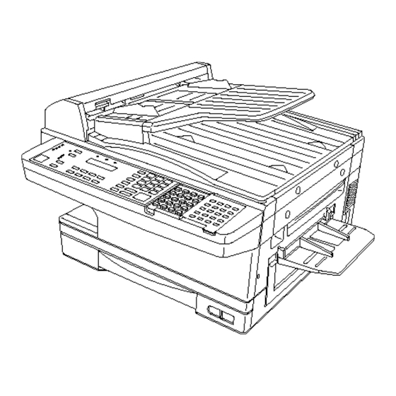
Section1 General Description 1.1 Product Description The OKIOFFICE 120 is a Multi-function product with flat bed scanner and Group 3 facsimile machine. Documents are printed on plain paper using dry electrophotographic printing. -
Page 9: Specifications
1.2 Applied regulations 1) EMI EN55022, EN50081-1, EN50082-1 2) Safety EN41003, EN60950 3) PTT NTR-3 4) EPA (United States Environmental Protection Agency) ENERGY STAR 1.3 Specifications 1.3.1 General specifications Item Specifications / Comments Type Multi-function product with flatbed scanner & high-speed facsimile transmitter and receiver Telephone network PSTN (Public Switched Telephone Network) or equivalent... -
Page 10: Scanning Specifications
Item Specifications / Comments Ambient temperature: 10 ° C to 32 ° C (50 to 89.6 degrees F) Environmental conditions Relative humidity: 20 % to 80 % with no condensation ± 10 %; 50/60 Hz Power requirements 230 V Power consumption Standby: 21 W Transmit:... -
Page 11: Printer Specifications
Item Spcifications / Comments Grayscale (Fax) 64 level. (128 level: only when using the non-memory transmission and the remote unit has 400 × 400 dpi print ability.) Grayscale (Copy) 128 level. Document contrast 5 levels (Manual adjustment) Original document feeding ADF section: Face up direction FBS section : Face down... -
Page 12: G3 Modem Section
1.3.5 G3 modem section Transmission mode V.17 V.33 Modulation method 128 Pt. 64 Pt. TCM 32 Pt. TCM 16 Pt. TCM 128 Pt. 64 Pt. TCM Transmission speed 14400 12000 9600 7200 14400 12000 (bit/s) Modulation speed 2400 2400 2400 2400 2400 2400... -
Page 13: Features And Functions
1.4. Features and Functions 1.4.1 Dialer Item Specifications / Comments Autodialer 200 total; 128 speed dial, 72 one-touch(8 programmable one-touch) (Up to 40 digits per location; 24 characters per location ID) Telephone index Select autodialer entries in LCD by Location ID name. Type of dialing Tone or pulse(10 pps) Dialing pause time... -
Page 14: Fax Receiving
SecureMail Using the ITU-T sub-address and password provide to SecureMail (ITU-T subaddress / communication not only with other OKIOFFICE 120 fax machines (or password) compatible brand), but fax machines of other manufactures as well. Up to 50 mailboxes for receiving, 4 digits passcode. -
Page 15: Copy
1.4.5 Copy Item Specifications / Comments Multiple copies Up to 99 with sorting Copy reduction and 50 % to 200 % at 1 % interval. enlargement rate Copy reduction rate Fixed value: 115, 122, 141, 172, 200% Copy enlargement rate Fixed value: 50, 70, 81, 86% Copy protect Available... -
Page 16: Supply Yields
1.5. Supply Yields Item Specifications / Comments Drum cartridge 10000 pages Toner cartridge 6000 pages Based on A4-sized sheets, 5 % document coverage and continuos printing. Transfer roller 30000 pages Fuser unit 60000 pages Stamp 30000 times 1.6 Option Item Specifications / Comments Paper supply unit A4 / A5 / A5R / B5;... -
Page 17: Dimensions
1.7 Dimensions Dimension in mm 1-10... -
Page 18: Keypad Layout
1.8 Keypad layout Here is a brief description of the keys on your fax machine and what they do, as well as a look at your machine’s indicator lights and their meanings. light — If glowing, indicates the transmission confirmation stamp feature (see page 2.6) is STAMP light —... - Page 19 — Starts a speed-dialling operation, which you finish by pushing three of the SPEED DIAL TEL INDEX keys on the numeric keypad. Also displays one-touch and speed dial entries sorted alphanumerically, as in a telephone directory. — Sets the fax for either A4-, B4-, A5R- or B5R-sized documents when you use BOOK DOC SIZE the flatbed scanner.
- Page 20 31. One-Touch Keys — The keys labelled 01-40 (or 41-80, if you’re using fliptab ) offer one-touch dialling convenience. You also can use the keys labelled 73-80, if you’re using fliptab , for programmable functions: this lets you teach your machine an advanced multi-step function just once, then recall the function at any time by pressing one of these keys.
-
Page 21: Front View
1.9 Front view 1. Liquid crystal display (LCD) — The display (2-line × 20-character) which shows the machine’s status and lets you see what you’re entering during various operations 2. Control Panel — The keys you use to operate your fax machine. (See pages 1.6–1.7 for more details.) 3. -
Page 22: Rear View
1.10 Rear view jack — Where you plug in the telephone line cord. (The other end of the cord plugs into a LINE wall telephone jack.) 2 jack — If you connect a second telephone to your machine, this is where you plug in the PHONE cord. -
Page 23: Id Label Specification
1.11 ID Label Specification 1.12 Labels location 1-16... -
Page 24: Section2 Machine Composition
Section2 Machine Composition 2.1 Interconnect Block Diagram... -
Page 26: Main Control Pcb
Discard used batteries according to the battery manufacturer’s instructions. OKI does not recommend the independent replacement of this battery. The battery is sold only as a component part of the main control PCB and cannot be purchased separately from OKI. - Page 27 The main control unit controls all function of the machine. Its component portions are: Fax Engine CPU - - - The CPU is the core of the control section. It controls all other sections. Scanner Control - - - Processes the signal from the Charge Coupled Device (CCD) such as magnification, reduction, and halftone.
-
Page 28: Ncu Pcb
2.3 NCU PCB The NCU PCB provides the connection to the telephone line. It consists of the interface circuit, dial pulse generator, ring signal detection and telephone control circuit. NCU PCB block diagram Major components of the NCU CML relay Connects the telephone line to the phone or fax. -
Page 29: Power Supply Unit (Psu)
2.4 Power Supply Unit (PSU) The power supply unit receives the input line voltage and currents it to output voltages of +5 VDC, +24 VDC, +12 VDC, and -12 VDC. The heater circuit controls output voltage to the fuser heater according to instructions received from the heater control circuit. -
Page 30: Sensors
2.5 Sensors 2.5.1 Sensor Locations The following illustration shows the relative positions of the machine’s sensors. 2.5.2 Sensor Descriptions The following table gives a brief description of each sensor and its function. Code Name Detects logic Sensor Type Document Sensor B4 Document size (B4) Detection Photo interrupter... - Page 31 Code Name Functions logic Sensor Type Paper Discharge Sensor Detects paper pass at paper exit. Detection: Photo interrupter Not detection: H HPES Hand Paper Empty Detects presence of recording paper in Detection: Photo interrupter Sensor multipurpose tray Not detection: H Paper Empty Sensor Detects presence of recording paper in No paper:...
-
Page 32: Document Scanning Sequence
2.6 Document Scanning Sequence 2.6.1 Document Detection When a document is placed into the document feeder, Document Sensor 1 (DS1) is activated and you will hear the short beep. 2.6.2 Document Separation Document separation is the process that allows a multi-page document to go through the scanner one page at a time. -
Page 33: Document Discharge
When DS2 detects the trailing edge of the document, the image signal output is turned off. The scanner continues to remain active for a few more seconds in case there is another document to follow. Document scanning in ADF section Document scanning in FBS section 2.6.5 Document Discharge The scanned document is discharged through the document exit by the exit roller... -
Page 34: Recording Section
2.7 Recording Section 2.7.1 Recording Paper Feed Path A sheet of the recording paper is separated from the remaining paper by the friction of the pickup roller. The paper is moved along the paper guide until it reaches the platen roller. Is then fed by the rotation of the platen roller. -
Page 35: Drum Charge
2.8.1 Drum Charge • The Drum is charged with static electricity before LED exposure. The Rotating Charge Brush is used for the charging method. • The rotating brush charging generate little ozone in the printer. Because the charge is directly given to the Drum, the Drum can be charged by low voltage. -
Page 36: Image Transfer
2.8.4 Image Transfer Image transfer is the process of transferring the toner image created on the Drum in the developing process to paper. We use the Roller Image Transfer instead of the Corona Image Transfer, as the image transfer method. In the Roller Image Transfer, there is little generation of ozone due to corona discharge. -
Page 37: Fusing
2.8.6 Fusing An Overview The toner image transferred on to the paper is securely fixed. A heat roller system is used as the fusing system. The toner image is fused by Heater Roller heated by the Heater Lamp, and securely fixed by the pressure between the Heater roller and Press rollers. A Thermistor detects and controls the Heater Roller temperature. - Page 38 Fusing temperature 1) Warming Up After the initialization of the printer, warming up of the printer starts and the Heater Lamp turns ON until the temperature of the Heater Roller reaches approx. 185 °C. 2) Printing When the printer obtains the printing command from its controller, the Heater Roller is maintained at 185 °C.
-
Page 39: Transmission Control Procedure (G3 Non Ecm Mode)
2.9 Transmission Control Procedure (G3 Non ECM mode) Transmitting Station Called Station Set Document Dial tone Set Dial Number Dial number Calling Answer Connect the line CNG(1100Hz) CED (2100Hz) NSF-CSI-DIS NSS-TSI-DCS Training FTT if training fails or FTT CFR if training Training/Fax Message succeeds Next page... -
Page 40: Transmission Control Procedure (G3 Non Ecm Mode, Polling)
2.10 Transmission Control Procedure (G3 Non ECM mode, polling) Transmitting Station Called Station Set Document Dial tone Set Dial Number Dial number Calling Answer Connect the line CNG(1100Hz) CED (2100Hz) NSF-CSI-DIS NSS-CIG-DTC NSS-TSI-DCS Training Training/Fax Message Next page (If multi-page transmission) Training/Fax Message Disconnect the line 2-17... -
Page 41: Transmission Control Procedure (G3, Ecm Mode)
2.11 Transmission Control Procedure (G3, ECM mode) Transmitting Station Called Station Set Document Dial tone Set Dial Number Calling Dial number Answer Connect the line CNG(1100Hz) CED(2100Hz) NSF-CSI-DIS NSS-TSI-DCS Training Training/Fax Message (ERROR) PPS-EOP Retransmission Training/Fax Message PPS-EOP (NO ERROR) Training/Fax Message Next block PPS-EOP... -
Page 42: Field Service Program Modes
Section3 Adjustment Procedures 3.1 Field Service Program Modes The fax machine feature maintenance modes for machine adjustment. Each mode is listed below along with the command used to activate the mode and a brief functional description. Set or Clear Machine Parameters ................PROGRAM, *, 0 Used to set or clear machine parameters. -
Page 43: Machine Parameter Adjustment
3.2 Machine Parameter Adjustment 3.2.1 Setting the Machine Parameters These switches are used to program internal machine parameters. The primary back up battery maintains these settings if power is lost. 1. From standby, press PROGRAM, *, 0. Set Parameters Program/Enter 2. -
Page 44: Machine Parameter A:0
Machine Parameter A:0 Initial Switch Adjust Usage/Comments Setting The country code enables the ROM to output the correct programming information for the respective country. Country code Machine Parameter A:1 Initial Switch Adjust Usage/Comments Setting Non-loaded cable compensation (TX) 0 db 4 db 8 db 12 db... -
Page 45: Machine Parameter A:2
Machine Parameter A:2 Initial Switch Adjust Usage/Comments Setting Factory use only Factory use only Factory use only Factory use only DTMF output level See table below. attenuation Machine Parameter A:2 … DTMF output level attenuation --- (Factory default is -8 dB) Switch Switch Switch... -
Page 46: Machine Parameter A:4
00111011 38.31 mm are factory set and should 00111100 38.96 mm not be adjusted unless 00111101 39.61 mm 40.26 mm ← Initial setting instructed by a OKI 00111110 technical representative. 00111111 40.91 mm 01000000 41.56 mm 01000001 42.21 mm 01000010 42.86 mm... -
Page 47: Machine Parameter A:7
Note: These values 00101010 27.27 mm 27.92 mm ← Initial setting are factory set and should 00101011 not be adjusted unless 00101100 28.57 mm instructed by a OKI 00101101 29.22 mm technical representative. 00101110 29.87 mm 00101111 30.52 mm 00110000 31.17 mm... -
Page 48: Machine Parameter B:0
Machine Parameter A:7 Initial Switch Adjust Usage/Comments Setting This switch indicates the DRAM capacity. This switch is read only, do not set any character. DRAM capacity indication You can see the memory capacity by how many “1” (This switch can indicate is indicated on the LCD. -
Page 49: Machine Parameter B:3
Note: These values 00001110 9.09 mm 9.74 mm ← Initial setting are factory set and should 00001111 not be adjusted unless 00010000 10.39 mm instructed by a OKI 00010001 11.04 mm technical representative. 00010010 11.69 mm 00010011 12.34 mm 00010100 12.99 mm... -
Page 50: Machine Parameter B:4
Note: These values 00011001 16.23 mm 16.88 mm ← Initial setting are factory set and should 00011010 not be adjusted unless 00011011 17.53 mm instructed by a OKI 00011100 18.18 mm technical representative. 00011101 18.83 mm 00011110 19.48 mm 00011111 20.13 mm... -
Page 51: Machine Parameter B:5
Machine Parameter B:2 Initial Switch Adjust Usage/Comments Setting ADF scanner registration Switch 76543210 Settings adjustment (Horizontal) 01111111 7.9 mm Maximum Adjusts the start point to scan the document. 00100000 2.0 mm The plus setting increase the left margin and the minus 00011000 1.5 mm setting decrease it. -
Page 52: Machine Parameter B:7
Machine Parameter B:4 Initial Switch Adjust Usage/Comments Setting Printer registration Switch 76543210 Settings adjustment (Vertical) 00001010 5.0 mm 00001001 4.5 mm 00001000 4.0 mm Adjusts the start point to 00000111 3.5 mm 00000110 3.0 mm print. 00000101 2.5 mm The plus setting increase the 00000100 2.0 mm 00000011... -
Page 53: Machine Parameter J:5
Machine Parameter B:6 Initial Switch Adjust Usage/Comments Setting Printer registration Switch 76543210 Settings adjustment (Horizontal) 00010100 20 mm at the optional second 00010011 19 mm cassette Adjusts the start point to print. 00000011 3 mm The plus setting increase the 00000010 2 mm left margin and the minus... -
Page 54: Machine Parameter J:7
Machine Parameter B:8 Initial Switch Adjust Usage/Comments Setting Printer registration Switch 76543210 Settings adjustment (Horizontal) 00010100 20 mm at the multipurpose tray 00010011 19 mm Adjusts the start point to print. 00000011 3 mm The plus setting increase the 00000010 2 mm left margin and the minus 00000001... - Page 55 Machine Parameter J:7 Initial Switch Adjust Usage/Comments Setting Slice level adjustment in Switch 76543210 SFine/HFine resolution. 10001010 Darkest setting 10000001 00001000 Default setting 00000001 00001010 Lightest setting Note: Do not exceed each maximum settings. Machine Parameter J:8 Initial Switch Adjust Usage/Comments Setting Slice level adjustment in...
-
Page 56: Memory Switch Adjustment
3.3 Memory Switch Adjustment 3.3.1 Setting the Memory Switches These switches are used to program internal machine parameters. The primary back up battery maintains these settings if power is lost. 1. From standby, press PROGRAM, *, 1. Set Memory Switch Program/Enter 2. -
Page 57: Memory Switch A:0 - Dialer
Memory Switch A:0 - Dialer Initial Switch Adjust Usage/Comments Setting Factory use only Factory use only Factory use only Factory use only DIS detect time after dialing Sets the time DIS signal is detected after dialing a 0: 55 sec number. -
Page 58: Memory Switch A:5 - Dialer
2.4 4.8 7.2 9.6 12 14.4 16.8 19.2 21.6 24 26.4 28.8 31.2 33.6 Note: It is maximum 33.6 kbps only when AL-100 optional module is attached to OKIOFFICE 120 model. Standard OKIOFFICE 120 model is maximum 14.4 kbps. 3-17... -
Page 59: Memory Switch B:1 - Transmission
Memory Switch B:1 - Transmission Initial Switch Adjust Usage/Comments Setting The time between reception of CFR and transmission of data When CFR and data overlap due to line echo, increase the interval between CFR and data transmission using this switch. 250 ms 500 ms 750 ms 1000 ms Switch 7 Switch 6... -
Page 60: Memory Switch B:2 - Transmission
Determines communication protocol. 0: V.17 1: V.33 Forced received print when Will force a remote OKIOFFICE 120 machine with memory transmitting from memory receive capabilities to print directly. This switch will 0: No prevent a memory overflow error at the remote 1: Yes unit. -
Page 61: Memory Switch B:5 - Transmission
2.4 4.8 7.2 9.6 12 14.4 16.8 19.2 21.6 24 26.4 28.8 31.2 33.6 Note: It is maximum 33.6 kbps only when AL-100 optional module is attached to OKIOFFICE 120 model. Standard OKIOFFICE 120 model is maximum 14.4 kbps. 3-20... -
Page 62: Memory Switch C:1 - Reception
Memory Switch C:1 - Reception Initial Switch Adjust Usage/Comments Setting Factory use only Factory use only Factory use only T1 timer 0: 35 sec 1: 20 sec Print image data when post If the received document includes the RTC, the unit message is not received after print the data even though the following protocol is receiving RTC signal... -
Page 63: Memory Switch D:0 - Reception
Memory Switch D:0 - Reception Initial Switch Adjust Usage/Comments Setting Number of HDLC end flags Defines the number of HDLC end flags. Switch 7 6 5 4 0 0 0 0 0 0 0 1 0 0 1 0 3 Default 0 0 1 1 0 1 0 0 0 1 0 1... -
Page 64: Memory Switch D:2 - Reception
Memory Switch D:2 - Reception Initial Switch Adjust Usage/Comments Setting EYE-Q slice level Setting this bit to “1” enables memory switch D:2, 0: Disable bits 0-3 and memory switch D:1, bits 0-7 and 1: Enable enables EYE-Q check adjustment. Check EYE-Q Set at 0: Line condition status (EYE-Q) is not 0: No checked after checking TCF. -
Page 65: Memory Switch E:0 - Scanner
Memory Switch E:0 - Scanner Initial Switch Adjust Usage/Comments Setting Factory use only Factory use only Factory use only Factory use only Factory use only Background level The background level measures the reflective 0: Automatic ability of scanned documents. 1: Fixed Effective scan width 0: A4=208 mm (8.2 ″... -
Page 66: Memory Switch G:1 - Remote Reception
Memory Switch G:1 - Remote reception Initial Switch Adjust Usage/Comments Setting Off-hook / on-hook detect Sets the time interval between the off-hook/on-hook time (remote reception) condition for remote reception. Switch 7 6 5 4 Time 0 0 0 0 0 ms 0 0 0 1 10 ms 0 0 1 0... -
Page 67: Memory Switch G:2 - Remote Reception
Memory Switch G:2 - Remote reception Initial Switch Adjust Usage/Comments Setting Factory use only Factory use only Factory use only Factory use only Switch-hook time If the switch hook is quickly depressed and released, switch-to-fax will occur. This setting adjusts how quickly the switch hook activation must Switch 3 2 1 0 Time 0 0 0 0... -
Page 68: Memory Switch H:0 - Operation
Memory Switch H:0 - Operation Initial Switch Adjust Usage/Comments Setting Display error line The number of error lines contained in the received 0: No data will be shown in the LCD. 1: Yes Total line monitor Allows fax communication to be heard through the 0: No monitor speaker. -
Page 69: Memory Switch H:2 - Operation
Memory Switch H:2 - Operation Initial Switch Adjust Usage/Comments Setting Factory use only Factory use only Factory use only Factory use only Factory use only Factory use only Erase polled document Determines if a document stored for polling is 0: No erased after being polled. -
Page 70: All Ram Clear
3.5 All RAM Clear The All RAM Clear setting will erase all user programmed information, all documents in memory, and reset the memory switches and machine parameters to factory defaults. This feature may also be used to try and clear a machine malfunction or lock up. If possible, when the All RAM Clear is used to reset a malfunction or lock up, it is advisable to print the machine settings, one-touch and speed dial listings to help in reprogramming this information. - Page 71 2.4 4.8 7.2 9.6 12 14.4 16.8 19.2 21.6 24 26.4 28.8 31.2 33.6 Note: It is maximum 33.6 kbps only when AL-100 optional module is attached to OKIOFFICE 120 model. Standard OKIOFFICE 120 model is maximum 14.4 kbps. Attribute 2 - Individual Autodialer Setting...
- Page 72 Determines communication protocol. 0: V.17 1: V.33 Forced received print when Will force a remote OKIOFFICE 120 machine with memory transmitting from memory receive capabilities to print directly. This switch will 0: No prevent a memory overflow error at the remote 1: Yes unit.
-
Page 73: Unique Switch Adjustment
3.7 Unique Switch Adjustment 3.7.1 Setting the Unique Switches These switches are used to program internal machine parameters. The primary back up battery maintains these settings if power is lost. 1. From standby, press PROGRAM, *, 4. Set Uniq Switch Program/Enter 2. -
Page 74: Unique Switch A:0 - Dialer
Unique Switch A:0 - Dialer Initial Switch Adjust Usage/Comments Setting Factory use only Congestion tone detection Setting this switch to “0” ignores telephone line 0: No congestion tones. 1: Yes Factory use only Factory use only Factory use only Factory use only Factory use only Factory use only Unique Switch A:1 ∼... -
Page 75: Unique Switch B:6 - Transmission
Unique Switch B:6 - Transmission Initial Switch Adjust Usage/Comments Setting Factory use only Factory use only Factory use only F-code sub-frame off Do not send the sub-address and password of F- 0: Send code box when a point of sending DCS signal after 1: Not send EOM signal. -
Page 76: Unique Switch C:1 - Reception
Unique Switch C:1 - Reception Initial Switch Adjust Usage/Comments Setting T1 timer adjustment When the unit switches to fax by on-hook transfer, the unit will seize the telephone line and attempt to handshake. Switch 7 5 6 4 Settings 0 0 0 0 0 0 0 1 0 0 1 0 0 0 1 1... -
Page 77: Unique Switch C:2 - Reception
Unique Switch C:2 - Reception Initial Switch Adjust Usage/Comments Setting Factory use only Factory use only Factory use only Factory use only Factory use only Junk Mode2 no TSI When block junk fax mode2 is set, determines if 0: Receive document the fax machine can not receive TSI signal. -
Page 78: Unique Switch E:4 - Scanner
Unique Switch E:4 - Scanner Initial Switch Adjust Usage/Comments Setting Factory use only Factory use only Factory use only Factory use only Leading edge document Sets the leading edge margin from the edge of margin settings for document to the start of the scanning position. ADF/FBS copying Switch 3 2 1 0 Settings... -
Page 79: Unique Switch E:5 - Scanner
Unique Switch E:5 - Scanner Initial Switch Adjust Usage/Comments Setting Leading edge document margin settings (ADF) Switch 7 6 5 4 Settings 0 1 1 1 4.55 mm Adjusts the leading edge 0 1 1 0 3.90 mm margin from the mirror 0 1 0 1 3.25 mm carriage passes End Sensor... -
Page 80: Unique Switch E:6 - Scanner
Unique Switch E:6 - Scanner Initial Switch Adjust Usage/Comments Setting Factory use only Factory use only Left edge document margin Switch 5 4 3 2 1 0 Settings adjustment upon scanning 0 0 0 0 0 0 0 mm using FBS 0 0 0 0 0 1 1 mm 0 0 0 0 1 0... -
Page 81: Unique Switch E:7 - Scanner
Unique Switch E:7 - Scanner Initial Switch Adjust Usage/Comments Setting Factory use only Factory use only Right edge document margin Switch 5 4 3 2 1 0 Settings adjustment upon scanning 0 0 0 0 0 0 0 mm using FBS 0 0 0 0 0 1 1 mm 0 0 0 0 1 0... -
Page 82: Unique Switch E:8 - Scanner
Unique Switch E:8 - Scanner Initial Switch Adjust Usage/Comments Setting Factory use only Factory use only Leading edge document Switch 5 4 3 2 1 0 Settings margin adjustment upon 0 0 0 0 0 0 0 mm scanning using FBS 0 0 0 0 0 1 1 mm 0 0 0 0 1 0... -
Page 83: Unique Switch E:9 - Scanner
Unique Switch E:9 - Scanner Initial Switch Adjust Usage/Comments Setting Factory use only Factory use only Trailing edge document Switch 5 4 3 2 1 0 Settings margin adjustment upon 0 0 0 0 0 0 0 mm scanning using FBS 0 0 0 0 0 1 1 mm 0 0 0 0 1 0... -
Page 84: Unique Switch F:0 - Printer
Unique Switch F:0 - Printer Initial Switch Adjust Usage/Comments Setting Factory use only Factory use only Smoothing in SFine (200 x 400 dpi) copy/receive mode 0: No 1: Yes Smoothing in Fine receive mode 0: No 1: Yes Smoothing in Fine copy Smoothes the data scanned in each resolution mode mode. -
Page 85: Unique Switch F:2 - Printer
Unique Switch F:2 - Printer Initial Switch Adjust Usage/Comments Setting Printer auto shut off time Time until the power supply turns the fusing unit off after printing has completed. Switch 7 6 5 4 3 2 1 0 Time 0 0 0 0 0 0 0 0 0 min 0 0 0 0 0 0 0 1 1 min... -
Page 86: Unique Switch F:5 - Printer
Unique Switch F:5 - Printer Initial Switch Adjust Usage/Comments Setting Factory use only Factory use only Factory use only Factory use only Factory use only Switch 2 1 Settings Print for saving the toner 25 % 50 % 75 % Primary copying upon Setting to “1”... - Page 87 Unique Switch F:7 and F:9 --- Factory use only 3-46...
-
Page 88: Unique Switch G:0 - Remote Reception
Unique Switch G:0 - Remote reception Initial Switch Adjust Usage/Comments Setting Factory use only Factory use only Factory use only Factory use only Factory use only Factory use only Manual transmit/receive Determines if transmitting or receiving manually using Start key after off-hook using Start key after off-hook of the second phone. -
Page 89: Unique Switch H:0 - Operation
Unique Switch H:0 - Operation Initial Switch Adjust Usage/Comments Setting Factory use only LCD error message After an error message has printed, the setting of 0: Remains in LCD this switch determines if the error message will 1: Returns to standby remain in the display. -
Page 90: Unique Switch H:3 - Operation
Unique Switch H:3 - Operation Initial Switch Adjust Usage/Comments Setting Use the key for When this switch is set to “1”, the REDUCT REDUCT confirmation stamp key functions as a confirmation stamp key in the Fax 0: No mode. 1: Yes Note: In U.K. -
Page 91: Printer Maintenance Mode
3.8 Printer maintenance mode In case of followings, use this mode. • When replaced the Fuser unit or Transfer roller. • When “Please Call Service” message appear in the LCD, access the this mode to determine the cause of the “Please Call Service” error message. q When you replace the Fuser unit or Transfer roller, you must set the count of replacement manually To access the printer maintenance modes:... -
Page 92: Print Program Mode List
3.9 Print Program Mode List This mode causes the unit to print a summary list of the unit’s programming modes. To print the program mode list press PROGRAM, *, 8. After printing the unit will return to standby. Program List ** Printing ** 3.10 Test Modes This mode offers the ability to print a test pattern and monitor certain unit output functions. - Page 93 If One-touch A is selected, you’ll see the following message on the LCD. Board Number? Use the numeric keypad to select the optional board number as shown in the following table. Numeric keypad Flash ROM on Main control Built-in CPU ROM * (asterisk) The software version of each board will be shown on the LCD.
-
Page 94: Printer Test
3.10.2 Printer Test The Printer Test mode offers three different test patterns. 1. Press PROGRAM, *, 9, PROGRAM, then press ENTER. Pattern 2. Press One-touch A, B or C to select the desired pattern. Pattern ** Printing The selected pattern will print continuously. Note: Press STOP to cancel the printing. -
Page 95: Feeder Test
3.10.4 Feeder test The feeder test discharges all documents in the automatic document feeder at a constant speed and displays the document total in the LCD. 1. Load test documents into the automatic document feeder. 2. Press PROGRAM, *, 9, PROGRAM three times, then press ENTER. Feeder Test 3. -
Page 96: Print Machine Parameters, Memory Switch And Unique Switch Settings
3.11 Print Machine Parameters, Memory Switch and Unique Switch Settings This function instructs the unit to print a list of the machine parameter, memory switch and unique switch settings. The list shows the default and current settings for each. After printing, the unit returns to standby. -
Page 97: Led Test
3.12.2 LED Test 1. Press PROGRAM, *, B. Then press One-touch B. All LEDs will turn on. Pressing START, toggle between All LEDs turn on and off. 2. Press STOP to exit the test mode. 3.12.3 LCD Test This mode displays two test patterns in LCD. 1. -
Page 98: Sram Check
3.12.5 SRAM Check This mode is used to test the SRAM memory where user programmed parameters such as date, time, TTI, etc are stored. Note: When this test is executed, an All RAM Clear will be performed by the unit. The All RAM Clear erases all user settings and resets all memory switches, machine parameters and unique switches to factory defaults. -
Page 99: Dram Check
If some portion of the read/write test fails, the display will show “NG”. M:NG 3. Press STOP to exit the test mode. 3.12.7 RTC(real time clock) Test This test mode is not applicable to field service of the OKIOFFICE 120 model. 3-58... -
Page 100: Line Tests
3.13 Line Tests This mode offers several internal tests and ability to monitor certain unit output functions. Included are relay tests, modem signal output monitoring, and DTMF output monitoring. 1. Press PROGRAM, *, C to enter the test mode. The tests are contained within three main menus. Relay Test Tonal Test DTMF Test... -
Page 101: Tonal Signal Test
3.13.2 Tonal Signal Test The tonal signal test permits the unit’s output tones to be monitored. Note: To monitor the tones, an external monitoring device must be connected to the telephone line jack. 1. Press PROGRAM, *, C, PROGRAM, ENTER. 2. -
Page 102: Dtmf Output Test
3.13.3 DTMF Output Test The DTMF output test permits the unit’s DTMF tones to be monitored. Note: To monitor the tones, an external monitoring device must be connected to the telephone line jack. 1. Press PROGRAM, *, C, PROGRAM two times, then press ENTER . DTMF 2. -
Page 103: Consumable Order Sheet
3.15 Consumable order sheet When the drum cartridge has reached its design life or the toner cartridge is empty, the machine prints the consumable sheet. Note: This feature’s default setting is OFF (not print the consumable sheet). (See Unique Switch H:3 to set ON this feature.) If using this feature, you should be enter following items: •... -
Page 104: Clear Consumable Order Sheet
10. The LCD will show: Customer’s Tel Enter the customer’s phone number. The phone number may be up to 20 characters in length. 11. Press ENTER to save the customer’s phone number and continue. 12. The LCD will show: Serial No. :Upper Enter the fax machine’s serial number. -
Page 105: Dram Clear
3.19 DRAM Clear Note: Perform a DRAM clear whenever a memory upgrade is added to the unit or the DRAM is replaced. 1. Press PROGRAM, *, I. DRAM Clear Program/Enter 2. Press ENTER. DRAM Clear Check Program/Enter 3. Press ENTER. The DRAM will be clear. Note: To finish the operation without performing initialization, press STOP or PROGRAM. -
Page 106: Section4 Troubleshooting Procedures
Section4 Troubleshooting Procedures 4.1 Troubleshooting Outline Before troubleshooting a unit check the following: • Is the power cord correctly connected to the machine? • Is the telephone handset and the telephone line cord connected correctly? • Is there paper in the paper cassette? •... -
Page 107: Recording Paper Jam
4.2 Recording Paper Jam Symptom: Recording paper did not exit paper cassette properly or jam occurred in print area. Suggested corrective action: 1. Verify that the recording paper conforms to the type specified for use in the machine and that has not been damaged or exposed to moisture. -
Page 108: Document Feeder Multi-Feeding Or Skew
4.4 Document Feeder Multi-feeding or Skew Symptom: Two or more pages of a multi-page document are fed at once. The document is fed on the skew. Slight skewing may sometimes occur. Suggested corrective action: 1. Verify that the original documents conform to the specifications designed for use in the machine and they are not damaged in any way. -
Page 109: Cannot Transmit
4.8 Cannot transmit Symptom: The unit will not transmit Suggested corrective action: 1. Verify the telephone line cord is properly installed and plugged into the correct type of wall jack. 2. Check for dial tone at the unit and wall jack. If no dial tone is present at the unit, check the NCU PCB. -
Page 110: Clearing Jammed Paper
4.11 Clearing Jammed Paper If the original document jams 1. If an original document jams, the LCD will show: Document Jam ContStor Enter/Cancl If you do wish to continue the operation, press ENTER and proceed step 2. To abort the operation, press CANCEL. This will delete from memory all pages stored during this operation, and the machine will return to the standby mode. -
Page 111: If A Printout Jams Inside Your Machine
If a printout jams inside your machine To clear a printout (either a received fax or a copy) jammed inside your fax machine: 1. Open the top cover. 2. Open the printer cover. 3. Remove the toner and drum cartridge. Important: Shield the drum cartridge from light, especially strong light. - Page 112 5. Re-set the toner and drum cartridge. 6. Gently close the printer cover. 7. Gently close the top cover, pressing firmly on the both sides of the top cover until you hear it click.
-
Page 113: If A Printout Jams Inside At A Paper Side Cover
If a printout jams inside at a paper side cover 1. Remove the multiple paper feed tray. 2. Open the side cover. 3. Carefully remove the jammed paper(s) from the machine. 4. Close the side cover back into its normal position. -
Page 114: The Image Quality Problems
4.12. The Image Quality Problems The following provides guidelines for troubleshooting the printer engine and actions to be taken. Before removing any portions of the machine or making any internal adjustments, be sure power to the unit is OFF. Suggested corrective actions should be performed in order as listed. Most conditions can be corrected by performing routine preventative maintenance steps. -
Page 115: Printout Too Light
4.12.3 Printout too light Symptom: Printed image is faint or does not print solid. Poor development • Remove the toner cartridge and shake it a few times to redistribute the toner inside. If the problem persists, replace the toner cartridge. •... -
Page 116: Uneven Print Density
4.12.6 Uneven print density Symptom: Image graduates from dark to light across page. Poor development • Remove the toner cartridge and shake it a few times to redistribute the toner inside. If the problem persists, replace the toner cartridge. • Replace the High Voltage Unit. •... -
Page 117: Toner Smudges
4.12.9 Toner Smudges Symptom: Background appears “peppered” with black spots. Poor scanning • Clean the Contact Grass. Improper fusing • Clean the Fusing Rollers. If it is not effective, replace Rollers or the Fusing Unit. 4-12... -
Page 118: Lcd Error Messages
4.13 LCD Error Messages Your fax machine’s LCD messages can help you spot problems. LCD error messages (Alphabetic list) What you see on the LCD What it means/What to do All Commands In Use Your fax machine has all of its 99 possible delayed commands (an automatic redialling counts as one) stored in memory and cannot accept another. - Page 119 Drum Near End Your drum will need to be replaced soon. Press to clear the message, then contact your authorised OKI dealer STOP to purchase a new drum cartridge if you do not already have one . Enter No. (0-32) You tried to enter a call group number greater than 32.
- Page 120 Mirror Carriage Error The mirror carriage of your machine has become inoperable. See page 4-3. Mirror Locked The transport mode is not turned off. Turn off the transport mode. No Command You pressed to review upcoming commands, but your REVIEW COMMANDS fax machine had none stored.
- Page 121 Enter a different sub-address. Toner Low Your fax machine is almost out of toner. Contact your authorised OKI dealer to purchase a new toner cartridge if you don’t already have one. Too Many Characters You attempted to enter too many numbers or other characters in the current operation.
-
Page 122: Error Codes
4.14 Error Codes If an error occurs during a communication, a check messages will be printed. The following provides an explanation of check messages. A possible solution to the problem • The sending location (if the remote fax stores a Location ID of its own) •... - Page 123 R.4.2 MPS/EOM/EOP was not received. Either the line disconnected before reception was completed or too many errors were detected by the receiving unit. Adjust the data error rate on Memory Switch C:0. It may also be necessary to decrease the receive communication speed via Memory Switch C:0.
- Page 124 Communication Error Messages The error messages on Check Message printouts can mean a variety of things. Here’s a brief summary: Error Message Possible Meanings Check condition of remote fax • Remote machine malfunctioned • No “handshake” signals from remote machine •...
-
Page 125: Service Call Error
4.15 Service Call Error When certain machine problems occur these message will appear in the LCD. 4.15.1 Call For Service Symptom: “Call For Service” is in the LCD. Suggested corrective action: 1. Verify the lamp turns on when the book cover open and close. 2. - Page 126 Heater Disconnect Symptom: broken or blown the heater lamp or thermistor in fuser unit. Suggested corrective action: 1. Check the connectors from the power supply to the main control PCB and to the fuser unit. 2. Check the heater lamp. If it comes on, see step 3; if it does not, see step 5. 3.
- Page 127 RX Motor Error Symptom: RX motor malfunction Suggested corrective action: 1. Verify the RX motor rotates when the power is on. 2. Check the connection between RX motor and the main control PCB (P56). (See page 2-2.) 3. Replace the RX motor if it doesn’t rotate. 4.
-
Page 128: Lcd Failure
4.16 LCD Failure Symptom: No display in the LCD. Suggested corrective action: 1. Verify that the power cord is correctly connected and the power switch is ON. 2. Check for a blown fuse or open circuit on the unit’s internal power supply. 3. -
Page 129: Cleaning The Unit
4.18 Cleaning the Unit Use a mild cleaning solution on a lint-free cloth to wipe the machine’s cover, handset and paper cassette tray. Never spray cleaner directly onto the fax machine as the spray could damage components inside the fax. Cleaning the Document Feeder Area If the unit is not feeding documents properly, perform this procedure: 1. -
Page 130: Cleaning The Fbs
Cleaning the FBS If you find your fax recipients complaining that the faxes you send are streaked, the inside of contact glass surface may be dirty. 1. Open the book cover. 2. Get soft, lint-free cloth with isopropyl alcohol. 3. Cleaning the FBS using the cloth with isopropyl alcohol. Cleaning the LED print head. - Page 131 Section5 Disassemble Before disassembling, disconnect the power cord and line cord. 5.1 Rear cover ..........................5-3 5.2 Shielding plate R........................5-3 5.3 Front cover ........................... 5-4 5.4 Upper right cover ........................5-4 5.5 Book cover..........................5-5 5.6 Upper rear cover ........................5-5 5.7 Upper left cover ........................
- Page 132 5.55 Speaker ..........................5-48 5.56 Rear cover B........................5-48 5.57 PES sensor........................5-49 5.58 PES sensor (optional paper supply unit)................5-50 5.59 Solenoid of optional paper supply unit ................5-51 5.60 Right cover........................5-52 5.61 HPES sensor / RCIL sensor....................5-53 5.62 PSS sensor / TOS sensor ....................
-
Page 133: Rear Cover
5.1 Rear cover 1. Open the top cover. 2. Remove the three rear cover mounting screws and disconnect the fan motor connector. 3. Release the four locking tabs, and then remove the rear cover. 5.2 Shielding plate R 1. Remove the rear cover. 2. -
Page 134: Front Cover
5.3 Front cover 1. Open the top cover. 2. Remove the front cover mounting screw. 3. Release the three locking tabs, and remove the front cover. 5.4 Upper right cover 1. Remove the four screw covers. 2. Remove the four upper right cover mounting screws, and then remove the upper right cover. -
Page 135: Book Cover
5.5 Book cover 1. Remove the three book cover mounting screws. 2. Remove the book cover. 5.6 Upper rear cover 1. Remove the book cover. 2. Remove the upper right cover. 3. Remove the screw cover. 4. Remove the five upper rear cover mounting screws, and then remove the upper rear cover. -
Page 136: Upper Left Cover
5.7 Upper left cover 1. Remove the two screw covers. 2. Remove the three upper left cover mounting screws, and then remove the upper left cover. 5.8 Upper front cover 1. Remove the upper right cover. 2. Open the book cover. 3. -
Page 137: Panel Lower Cover
5.9 Panel lower cover 1. Open the top cover. 2. Remove the protection sheet until the screw appears. 3. Remove the three panel lower cover mounting screws. 4. Disconnect the three connectors (other than the speaker connector) on the connect B PCB. 5. -
Page 138: Ps Fan Motor And Ps Fan Motor Cover
5.10 PS fan motor and PS fan motor cover 1. Remove the rear cover. 2. Remove the two PS fan motor mounting screws, and then remove the PS fan motor. 3. Release the three locking tabs, and then remove the PS fan motor cover. -
Page 139: Connect A Pcb
5.11 Connect A PCB 1. Remove the rear cover. 2. Remove the shielding plate R. 3. Disconnect the connectors on the connect A PCB. 4. Remove the two connect A PCB mounting screws, and then remove the connect A PCB. 5.12 NCU PCB 1. -
Page 140: Main Control Pcb
5.13 Main control PCB 1. Remove the rear cover. 2. Remove the shielding plate R. 3. Remove the connect A PCB. 4. Remove the NCU PCB. 5. Disconnect the connectors on the main control PCB. 6. Remove the two main control PCB mounting screws. 7. -
Page 141: Modem Pcb
5.14 Modem PCB 1. Remove the rear cover. 2. Remove the shielding plate R. 3. Remove the connect A PCB. 4. Remove the NCU PCB. 5. Remove the two main control PCB mounting screws and disconnect the connector between the main control PCB and the modem PCB by sliding the main control PCB toward left. -
Page 142: Power Supply Unit
5.16 Power supply unit 1. Remove the rear cover. 2. Remove the two modular bracket mounting screws, and then remove the modular bracket. 3. Disconnect the three connectors on the power supply unit. 4. Remove the ground wire mounting screw. 5. -
Page 143: Power Switch Assembly
5.17 Power switch assembly 1. Remove the rear cover. 2. Remove the ground wire mounting screw. 3. Disconnect the connector (CN1) on the power supply unit. 4. Remove the two power switch bracket mounting screws, and then remove the power switch assembly. -
Page 144: Duct And Inside Fan Motor
5.18 Duct and Inside fan motor 1. Remove the rear cover. 2. Remove the shielding plate R. 3. Remove the connect A PCB. 4. Remove the NCU PCB. 5. Remove the modem PCB. 6. Disconnect the connector (P50) on the main control PCB. 7. -
Page 145: Cover Switch
5.19 Cover switch 1. Remove the panel lower cover. 2. Remove the shielding plate R. 3. Remove the connect A PCB. 4. Remove the NCU PCB. 5. Remove the main control PCB. 6. Remove the two cover switch mounting screws, and then remove the cover switch. 5-15... -
Page 146: High Voltage Unit
5.20 High voltage unit 1. Remove the front cover. 2. Remove the two shielding plate F mounting screws, and then remove the shielding plate F. 3. Disconnect the connector and remove the four high voltage unit mounting screws. 4. Remove the high voltage unit. Note: When attaching the high voltage unit to the unit, be sure to contact vertically the high voltage point and the point of contact on the back side of the high voltage unit. -
Page 147: Home Sensor
5.21 Home sensor 1. Remove the panel lower cover. 2. Disconnect the home sensor connector (P11) on the connect B PCB. 3. Remove the home sensor mounting screw, and then remove the home sensor. 5.22 End sensor 1. Remove the panel lower cover. 2. -
Page 148: Gas Spring
5.23 Gas spring 1. Remove the panel lower cover. 2. Remove the front cover 3. Remove the two E-rings, and then remove the gas spring. Note: Do not throw the changed gas spring into the fire. 5-18... -
Page 149: Book Scanner Glass
5.24 Book scanner glass 1. Remove the upper right cover. 2. Remove the upper front cover mounting screw under the upper right cover. 3. Remove the book scanner glass. Note: If it is hard to remove the book scanner glass, remove the upper front cover. Note: When attaching the book scanner glass to the unit, be sure to insert it under the projection. -
Page 150: Book Cover Pad
5.25 Book cover pad 1. Open the book cover. 2. Remove the used pad which is attached to book cover by the adhesive tapes. 3. Set the corner of the new pad at the front right corner of the book scanner glass. 4. -
Page 151: Tx Cover
5.27 Tx cover 1. Open the scanner cover. 2. Remove the two Tx cover mounting screws. 3. Release the four locking tabs, and remove the Tx cover. 5.28 ADF assembly 1. Remove the book cover. 2. Remove the upper right cover. 3. - Page 152 10. Remove the lock lever retainer mounting screw. 11. Remove the screw of which attach the upper front cover. 12. Remove the three ADF assembly mounting screws, and then remove the ADF assembly. 5-22...
-
Page 153: Guide Supporter
5.29 Guide supporter 1. Remove the Tx cover. 2. Remove the four guide supporter mounting screws, and then remove the guide supporter. 5-23... -
Page 154: Separator Roller Assembly
5.30 Separator roller assembly 1. Remove the Tx cover. 2. Remove the guide supporter. 3. Remove the three E-rings. 4. Remove the gear. 5. Remove the bearings, and then remove the separator roller assembly. 5-24... -
Page 155: Document Sensor 2 (Ds2)
5.31 Document sensor 2 (DS2) 1. Remove Tx cover. 2. Remove the guide supporter. 3. Disconnect the connector on the DS2. 4. Release the locking tabs, and then remove the DS2. 5.32 Press roller 1. Remove the Tx cover. 2. Remove the guide supporter. 3. -
Page 156: Tx Cover Release Lever
5.33 Tx cover release lever 1. Remove the Tx cover. 2. Remove the guide supporter. 3. Remove the release lever with sliding it. 5.34 ADF interlock 1. Remove the rear cover. 2. Remove the shielding plate R. 3. Disconnect the interlock connector (P16) on the connect A PCB. 4. - Page 157 2. Remove the book cover. 3. Remove the upper rear cover. 4. Remove the Tx cover. 5. Open the scanner cover. 6. Remove the stopper. 7. Remove the three gear cover mounting screws, and then remove the gear cover. 8. If the E-ring is attached to the gear you want to remove, remove the gear after removing its E-ring. 5-27...
-
Page 158: Inner Guide B
5.36 Inner guide B 1. Remove the Tx cover. 2. Open the scanner cover. 3. Remove the stopper. 4. Remove the seven inner guide B mounting screws, and then remove the inner guide B. 5.37 Sensors (DA3, DS1, DB4) 1. Remove the Tx cover. 2. -
Page 159: Exit Roller
5.38 Exit roller 1. Remove the upper right cover. 2. Remove the book cover. 3. Remove the upper rear cover. 4. Remove the Tx cover. 5. Open the scanner cover. 6. Remove the stopper. 7. Remove the gear cover. 8. Remove the inner guide B. 9. -
Page 160: Feed Roller Assembly/Retard Roller Assembly
5.39 Feed roller assembly/Retard roller assembly 1. Remove the upper right cover. 2. Remove the book cover. 3. Remove the upper rear cover. 4. Remove the Tx cover. 5. Open the scanner cover. 6. Remove the stopper. 7. Remove the gear cover. 8. -
Page 161: Outer Guide B
5.40 Outer guide B 1. Remove the ADF assembly. 2. Open the scanner cover. 3. Remove the stopper. 4. Remove the four outer guide B mounting screws, and then remove the outer guide B. 5.41 ADF permit sensor (APS) 1. Remove the ADF assembly. 2. -
Page 162: Press Roller
5.42 Press roller 1. Remove the ADF assembly. 2. Open the scanner cover. 3. Remove the stopper. 4. Remove the outer guide B. 5. Remove the press spring B, and then remove the press roller. 5.43 Exit press roller 1. Remove the ADF assembly. 2. -
Page 163: Confirmation Stamp
5.44 Confirmation stamp 1. Remove the rear cover. 2. Remove the shielding plate R. 3. Disconnect the confirmation stamp connector (P19) on the connect A PCB. 4. Remove the ADF assembly. 5. Open the scanner cover. 6. Remove the stopper. 7. -
Page 164: Base Frame Assembly
5.46 Base frame assembly 1. Remove the ADF assembly. 2. Open the scanner cover. 3. Remove the stopper. 4. Remove the outer guide B. 5. Remove the six E-rings and remove the hinge shaft. 6. Remove the base frame assembly. 5-34... -
Page 165: Pickup Roller
5.47 Pickup roller 1. Pull out the paper cassette. 2. Turn the pickup roller until the pickup roller appears, and then remove the pickup roller. Note: When attaching the pickup roller to the unit, insert the pin of the pickup roller pad into the hole of the shaft. -
Page 166: Adf Motor And Fbs Motor
5.48 ADF motor and FBS motor 1. Remove the upper right cover. 2. Remove the book cover. 3. Remove the upper rear cover. 4. Remove the upper left cover. 5. Remove the hinge retainer mounting screw and release the hook with turning the hinge retainer. 6. - Page 167 9. Remove the three pulley bracket mounting screws, and then remove the pulley bracket. 10. Remove the four FBS motor mounting screws, and then remove the FBS motor. 5-37...
- Page 168 How to re-attach the motor: 1. Attach the FBS motor to the pulley bracket using the motor’s four screws. 2. Attach the pulley bracket to the motor bracket using the pulley bracket’s three screws temporarily. 3. Attach the ADF motor to the motor bracket using the motor’s three screws. 4.
-
Page 169: Inverter Pcb
5.49 Inverter PCB 1. Remove the upper right cover. 2. Remove the book scanner glass. 3. Release the two locking tabs, and then remove the inverter cover. 4. Disconnect the two connectors on the inverter PCB 5. Remove the two inverter PCB mounting screws, and then remove the inverter PCB. 5-39... -
Page 170: Mirror Carriage A And B
5.50 Mirror carriage A and B 1. Remove the book cover. 2. Remove the upper right cover. 3. Remove the upper rear cover. 4. Remove the upper front cover. 5. Remove the book scanner glass. 6. Remove the five FBS scanner cover mounting screws, and then remove the FBS scanner cover. 7. - Page 171 8. Remove the each two mirror carriage A and B mounting screws. 9. Remove the inverter cover. 10. Disconnect the mirror carriage A connector on the inverter PCB. 11. Remove the mirror carriage A. 12. Remove the mirror carriage B. 5-41...
- Page 172 How to re-attach the mirror carriage A and B: 1. Fit the mirror carriage A to the slider on the belt holder. 2. Attach the mirror carriage A and B using each two screws temporarily. 3. Turn the FBS motor to fit the four holes to set the mirror carriage A and B. 4.
- Page 173 If the inverter belt is off the belt holder: 1.Turn the FBS motor to fit the hole on the inverter holder. 2. Put the belt on the belt holder. Note: If the belt for the mirror carriage is off the belt holder, put the belt on the belt holder when fitting the four holes to set the mirror carriage.
-
Page 174: Lamp
5.51 Lamp 1. Remove the book cover. 2. Remove the upper right cover. 3. Remove the upper rear cover. 4. Remove the upper front cover. 5. Remove the book scanner glass. 6. Remove the mirror carriage A. 7. Remove the cable link A mounting screw, and then remove the cable link A. 8. -
Page 175: Mirror A And B
5.52 Mirror A and B 1. Remove the book cover. 2. Remove the upper right cover. 3. Remove the upper rear cover. 4. Remove the upper front cover. 5. Remove the book scanner glass. 6. Remove the mirror carriage A and B. 7. -
Page 176: Control Panel Pcb 1 And 2
5.53 Control panel PCB 1 and 2 1. Remove the panel lower cover. 2. Remove the four control panel assembly. 3. Disconnect the three connectors on the control panel PCB 1. 4. Remove the fourteen control panel PCB 1 mounting screws and remove the seven control panel PCB 2 mounting screws. -
Page 177: Lcd Assembly
5.53 LCD assembly 1. Remove the panel cover. 2. Remove the control panel PCB1 and 2. 3. Remove the two LCD assembly mounting screws, and then remove the LCD assembly. 5.54 Connect B PCB 1. Remove the panel lower cover. 2. -
Page 178: Speaker
5.55 Speaker 1. Remove the panel lower cover. 2. Remove the connector from the connect B PCB. 3. Remove the two speaker mounting screws, and then remove the speaker. 5.56 Rear cover B Note: This procedure effects only when optional paper supply unit has been attached. 1. -
Page 179: Pes Sensor
5.57 PES sensor 1. Pull the paper cassette completely out of the paper supply unit. 2. Remove the two PES sensor mounting screws. 3. Remove the connector from PES sensor. 5-49... -
Page 180: Pes Sensor (Optional Paper Supply Unit)
5.58 PES sensor (optional paper supply unit) Note: This procedure effects only when optional paper supply unit has been attached. 1. Remove the optional paper supply unit. a. Remove the rear cover B of the optional paper supply unit. b. Remove the connector from the upper connector on the connector PCB. c. -
Page 181: Solenoid Of Optional Paper Supply Unit
5.59 Solenoid of optional paper supply unit Note: This procedure effects only when optional paper supply unit has been attached. 1. Remove the optional paper supply unit. a. Remove the rear cover B of the optional paper supply unit. b. Remove the connector from the upper connector on the connector PCB. c. -
Page 182: Right Cover
5.60 Right cover 1. Move the front cover by loosen a front cover mounting screw. 2. Remove the screw cover then remove the two right cover mounting screws. 3. Remove the right cover. 5-52... -
Page 183: Hpes Sensor / Rcil Sensor
5.61 HPES sensor / RCIL sensor 1. Remove the right cover. 2. Remove the rear cover. 3. Remove shielding cover R. 4. Disconnect the P61 connector from the main control PCB. 5. Open the printer cover, then remove the drum/toner cartridge. 6. -
Page 184: Pss Sensor / Tos Sensor
5.62 PSS sensor / TOS sensor 1. Open the top cover. 2. Open the printer cover, then remove the drum/toner cartridge. 3. Remove the two TOS sensor mounting screws and disconnect the connector, then remove the TOS sensor. 4. Remove a PSS sensor mounting screw and disconnect the connector, then remove the PSS sensor. -
Page 185: Transfer Roller
5.63 Transfer roller Note: When you replace the transfer roller, you must set the count of replacement manually. See “Printer maintenance mode”, page 3-50. 1. Open the top cover. 2. Open the printer cover, then remove the drum/toner cartridge. 3. Pry a transfer roller off, as shown below. 5.64 Lock lever 1. -
Page 186: Led Print Head
5.65 LED print head 1. Open the top cover. 2. Open the printer cover. 3. Pushing up the LED print head and remove the two E-rings, then remove the LED print head. 4. Disconnect the two connectors from the LED print head. 5-56... -
Page 187: Paper Guide
5.66 Paper guide 1. Remove the two paper guide mounting screws. 2. Remove the paper guide. 5.67 PDS sensor 1. Open the top cover. 2. Open the printer cover, then remove the drum/toner cartridge. 3. Remove the two paper guide mounting screws, then remove the paper guide. 4. -
Page 188: Fuser Unit
5.68 Fuser unit Note: When you replace the fuser unit, you must set the count of replacement manually. See “Printer maintenance mode”, page 3-50. 1. Open the top cover. 2. Remove the rear cover. 3. Disconnect the CN2 connector from the power supply unit. 4. -
Page 189: Feed Roller B
5.69 Feed roller B 1. Open the top cover. 2. Open the printer cover, then remove the drum/toner cartridge. 3. Remove the press roller B mounting screw, the remove the press roller B. 4. Pry a feed roller B off. 5-59... - Page 190 Note: If you re-attach the feed roller B, put the right and left nibs into the fixing hole as shown. 5-60...
-
Page 191: Feed Roller C
5.70 Feed roller C 1. Open the top cover. 2. Remove the rear cover. 3. Remove the shielding plate R. 4. Remove the connect A PCB, NCU PCB, Main control PCB and Modem PCB. 5. Remove the duct and inside fan motor. 6. - Page 192 1. Open the top cover. 2. Remove the rear cover. 3. Remove the shielding plate R. 4. Remove the connect A PCB, NCU PCB, Main control PCB and Modem PCB. 5. Remove the duct and inside fan motor. 6. Remove the modular bracket, 7.
-
Page 193: Rx Motor
5.72 RX motor 1. Open the top cover. 2. Remove the rear cover. 3. Remove the shielding plate R. 4. Remove the connect A PCB, NCU PCB, Main control PCB and Modem PCB. 5. Remove the duct and inside fan motor. 6. -
Page 194: Cassette Pcb
5.73 Cassette PCB 1. Remove the upper left cover. 2. Open the top cover. 3. Remove the front cover. 4. Remove the two RX exit cover B mounting screws, then remove the RX exit cover B. 5. Remove a RX exit cover A mounting screws, then remove the RX exit cover A. 6. - Page 195 10. Move the cassette PCB by sliding it. 11. Disconnect the all connectors on the cassette PCB. 5-65...
-
Page 196: Cassette Rail
5.74 Cassette rail 1. Pull the paper cassette completely out of the machine. 2. Remove the three cassette rail L mounting screws, then remove the cassette rail L. 3. Remove a cassette rail R mounting screw, then remove the cassette rail R. 5-66... -
Page 197: Cassette Pcb / Connect Pcb
5.75 Cassette PCB / Connect PCB Note: This procedure effects only when optional paper supply unit has been attached. 1. Remove the rear cover B of the optional paper supply unit. 2. Remove the two cassette PCB mounting screws and disconnect the all connector on the cassette PCB, then remove the cassette PCB.
Need help?
Do you have a question about the OKIOFFICE 120 and is the answer not in the manual?
Questions and answers