Table of Contents
Advertisement
Quick Links
Advertisement
Table of Contents

Related Manuals for Pilz PSEN cs5.1n


Summary of Contents for Pilz PSEN cs5.1n
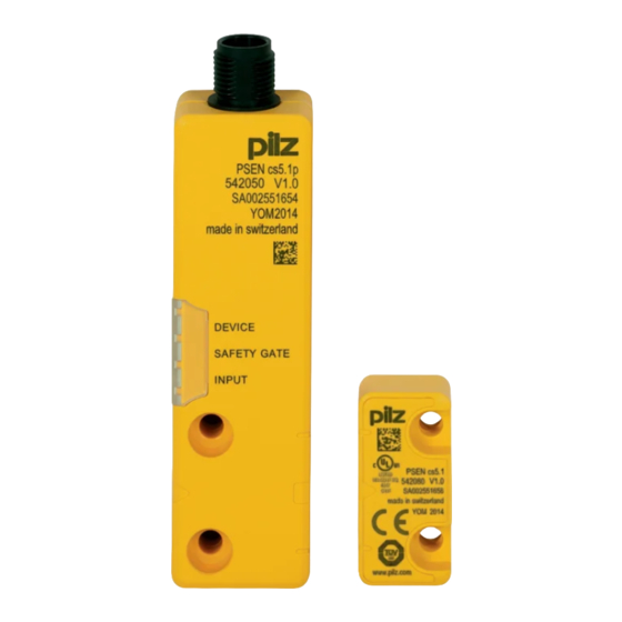
- Page 1 PSEN cs5.1n PSEN sensor technology Operating Manual-1003427-EN-05...
- Page 2 Preface This document is the original document. All rights to this documentation are reserved by Pilz GmbH & Co. KG. Copies may be made for the user's internal purposes. Suggestions and comments for improving this documenta- tion will be gratefully received.
-
Page 3: Table Of Contents
Operating distances Lateral and vertical offset Wiring Pin assignment, connector and cable Connection to evaluation devices Single connection Connection to Pilz evaluation devices Teaching in the actuator Installation Use in operating heights higher than 2000 m above sea level Adjustment Operation... - Page 4 Contents Order reference System Accessories EC declaration of conformity Operating Manual PSEN cs5.1n 1003427-EN-05...
-
Page 5: Introduction
PSEN cs5.1n Introduction Validity of documentation This documentation is valid for the product PSEN cs5.1n. It is valid until new documentation is published. This operating manual explains the function and operation, describes the installation and provides guidelines on how to connect the product. -
Page 6: Safety
If installed in other environments, measures should be taken to comply with the applicable standards and directives for the respective installation site with regard to in- terference. Operating Manual PSEN cs5.1n 1003427-EN-05... -
Page 7: Safety Regulations
In safety-related applications, please comply with the mission time T in the safety-re- lated characteristic data. When decommissioning, please comply with local regulations regarding the disposal of electronic devices (e.g. Electrical and Electronic Equipment Act). Operating Manual PSEN cs5.1n 1003427-EN-05... -
Page 8: For Your Safety
The guaranteed safe operating distances for the specified selections only apply when the actuator approaches the switch vertically. With the other approach directions, the operating distances may sometimes be considerably larger (particularly when ap- proaching the semicircle). Operating Manual PSEN cs5.1n 1003427-EN-05... -
Page 9: Function Description
The safety outputs may have a high or low signal, depending on the position of the actu- ator. State of the outputs: Actuator in the re- sponse range Safety output 12 Safety output 22 Signal output Y32 High High High Block diagram Power Receiver Actuator Operating Manual PSEN cs5.1n 1003427-EN-05... -
Page 10: Operating Distances
Typical release distance: 14 mm [2] Actuator aligned to the triangle marking on the switch Assured operating distance: 4 mm Assured release distance: 12 mm Typical operating distance: 5 mm Typical release distance: 8 mm Operating Manual PSEN cs5.1n 1003427-EN-05... - Page 11 PSEN cs5.1n [3] Actuator aligned to the semicircle marking on the switch Assured operating distance: 3 mm Assured release distance: 16 mm Typical operating distance: 6 mm Typical release distance: 8 mm Operating Manual PSEN cs5.1n 1003427-EN-05...
-
Page 12: Lateral And Vertical Offset
-8 -4 0 -12 -8 -4 0 Legend [1] Hysteresis [2] Typical operating distance S [3] Typical release distance S [4] Offset in mm [5] Operating distance in mm [6] Response range [7] Status of LED Operating Manual PSEN cs5.1n 1003427-EN-05... - Page 13 Legend [1] Hysteresis [2] Typical operating distance S [3] Typical release distance S [4] Offset in mm [5] Operating distance in mm [6] Response range [7] Status of LED [8] Square marking [9] Triangle marking Operating Manual PSEN cs5.1n 1003427-EN-05...
- Page 14 [8] Limit of response range, position of gate hinge [9] Status of LED [10] Sensing face of the actuator, labelled with Pilz logo [11] Distance from the front edge of the sensor to the limit of the response range (position if the gate end stop) = 15.9 mm...
- Page 15 Alignment 3: Actuator aligned to the semicircle marking on the switch 8 4 0 8 4 0 Legend [1] Hysteresis [2] Typical operating distance S [3] Typical release distance S [4] Offset in mm [5] Operating distance in mm [6] Response range Operating Manual PSEN cs5.1n 1003427-EN-05...
-
Page 16: Wiring
Output, channel2 black Signal output grey The wire colour also applies for the cable available from Pilz as an accessory. Connection to evaluation devices Make sure that the selected evaluation device has the following properties: 2-channel with feasibility monitoring OSSD signals are evaluated Operating Manual PSEN cs5.1n... -
Page 17: Single Connection
Actuator Receiver Evaluation device Connection to Pilz evaluation devices The safety switch PSEN cs5.1n can be connected to Pilz evaluation devices, for example. Suitable Pilz evaluation devices are, for example: PNOZelog for safety gate monitoring PNOZpower for safety gate monitoring... -
Page 18: Teaching In The Actuator
PSENcode PNOZ s3 PNOZmulti PNOZmulti PSENcode 5 Y32 Legend: Input OSSD Input OSSD Signal input Teaching in the actuator Any approved Pilz actuator is detected as soon as it is brought into the response range. Operating Manual PSEN cs5.1n 1003427-EN-05... -
Page 19: Installation
The actuator should be protected from unauthorised removal and from contamination. Close the mounting holes using the seals provided (see diagrams). The use of seals should be regarded as equivalent to using permanent fastenings in accordance with Clause 7.2c of EN ISO 14119. Operating Manual PSEN cs5.1n 1003427-EN-05... - Page 20 Fig.: Seals [1]: 4 seals for actuators [2]: 2 seals for actuators [3]: 2 seals for actuators [4]: 2 seals for switches and 2 seals for actuators Fig.: Applying the screw cover [4] on the switch Operating Manual PSEN cs5.1n 1003427-EN-05...
- Page 21 [4] Offset in mm (distance of the middle of the actuator to the zero line in the grid) [5] Operating distance in mm [6] Response range [7] Connector on the sensor [8] Limit of response range, position of gate hinge [9] Status of LED Operating Manual PSEN cs5.1n 1003427-EN-05...
-
Page 22: Use In Operating Heights Higher Than 2000 M Above Sea Level
7. Align the actuator and tighten the screws. Use in operating heights higher than 2000 m above sea level When using the PSEN cs5.1n note the reduced max. ambient temperature of +60 °C at a height of 2000 m to 4000 m. -
Page 23: Operation
[ 26]. Display not Display not Supply voltage is at Ensure the voltage supply definitive definitive the limit of the toler- corresponds to the Tech- ance range yellow nical details [ 26]. Operating Manual PSEN cs5.1n 1003427-EN-05... -
Page 24: Dimensions In Mm
Display not Wrong actuator Use the actuator PSEN definitive cs5.1 M12. green yellow Switch doesn't start Change the switch. yellow yellow Dimensions in mm Safety switch DEVICE SAFETY GATE INPUT 26,4 Actuator Operating Manual PSEN cs5.1n 1003427-EN-05... - Page 25 PSEN cs5.1n Legend: [1] Square marking [2] Triangle marking [3] LEDs [4] Semicircle marking Operating Manual PSEN cs5.1n 1003427-EN-05...
-
Page 26: Technical Details
Lowest operating current 2 mA Utilisation category in accordance with EN 60947-1 DC-12 Times Test pulse duration, safety outputs 150 µs Switch-on delay after UB is applied Actuator typ. 30 ms Actuator max. 50 ms Operating Manual PSEN cs5.1n 1003427-EN-05... - Page 27 Rated insulation voltage 75 V Rated impulse withstand voltage 1 kV Protection type Housing IP66, IP67 Mechanical data Actuator 1 PSEN cs5.1 M12 Operating distances Repetition accuracy switching distances Change of operating distance with temperature changes +-0,02mm/°C Operating Manual PSEN cs5.1n 1003427-EN-05...
- Page 28 Actuator dimensions Height 18 mm Width 37 mm Depth 19 mm Weight of safety switch 68 g Weight of actuator 15 g Weight 83 g Where standards are undated, the 2015-11 latest editions shall apply. Operating Manual PSEN cs5.1n 1003427-EN-05...
-
Page 29: Safety Characteristic Data
2) this product must accept any interference received, including interference that may cause undesired operation. Changes or modifications made to this product not expressly approved by Pilz may void the FCC authorization to operate this equipment. NOTE: This equipment has been tested and found to comply with the limits for a Class A digital device, pursuant to Part 15 of the FCC Rules. - Page 30 380 213 10 m 380 214 30 m 380 215 PSEN cable M12-5sf Straight, M12, 5-pin, socket Open cable 630 310 630 311 10 m 630 312 20 m 630 298 30 m 630 297 Operating Manual PSEN cs5.1n 1003427-EN-05...
- Page 31 European Parliament and of the Council. 2006/42/EC on machines 2014/53/EC on radio equipment The complete EC Declaration of Conformity is available on the Internet at www.pilz.com/ downloads. Representative: Norbert Fröhlich, Pilz GmbH & Co. KG, Felix-Wankel-Str. 2, 73760 Ost- fildern, Germany Operating Manual PSEN cs5.1n...
- Page 32 Back cover Support Technical support is available from Pilz round the clock. Americas Australia Scandinavia Brazil +61 3 95600621 +45 74436332 +55 11 97569-2804 Spain Canada Europe +34 938497433 +1 888-315-PILZ (315-7459) Austria Switzerland Mexico +43 1 7986263-0 +41 62 88979-30...
Need help?
Do you have a question about the PSEN cs5.1n and is the answer not in the manual?
Questions and answers