Table of Contents
Advertisement
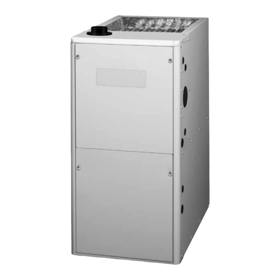
Two-Stage Condensing Gas Furnaces With Fixed & Variable Speed Blowers
INSTALLATION INSTRUCTIONS
*TE Upflow Only Furnace
• Failure to follow safety warnings exactly could result in serious injury, death or property
damage.
• Installation and service must be performed by a qualified installer, service agency or the gas
supplier.
• Do not store or use gasoline or other flammable vapors and liquids in the vicinity of this or
any other appliance.
• Do not try to light any appliance.
• Do not touch any electrical switch; do not use any phone in your building.
• Leave the building immediately.
• Immediately call your gas supplier from a neighbors phone. Follow the gas suppliers instructions.
• If you cannot reach your gas supplier, call the fire department.
DO NOT DESTROY. PLEASE READ CAREFULLY & KEEP IN A SAFE PLACE FOR FUTURE REFERENCE.
WARNING
FIRE OR EXPLOSION HAZARD
WHAT TO DO IF YOU SMELL GAS
*TN Downflow Furnace
96.0% AFUE
Advertisement
Table of Contents

Related Manuals for Nortek FG7TE-FS


Summary of Contents for Nortek FG7TE-FS
- Page 1 Two-Stage Condensing Gas Furnaces With Fixed & Variable Speed Blowers 96.0% AFUE INSTALLATION INSTRUCTIONS *TE Upflow Only Furnace *TN Downflow Furnace WARNING FIRE OR EXPLOSION HAZARD • Failure to follow safety warnings exactly could result in serious injury, death or property damage.
-
Page 2: Table Of Contents
TABLE OF CONTENTS IMPORTANT SAFETY INFORMATION ......3 Blower Speed Configuration ..........25 Fixed Speed Blower Applications ........25 REQUIREMENTS & CODES ..........4 Variable Speed Blower Applications ......25 Combustion Air Quality ............5 Dehumidification Options ..........26 Heating Load ..............5 Heat Anticipator ...............26 Installation in a Garage ............5 Clearances to Combustible Materials ......6 START-UP &... -
Page 3: Important Safety Information
IMPORTANT SAFETY INFORMATION WARNING: INSTALLER: Please read all instructions before servicing this equipment. Pay attention to all safety warnings and Improper installation, service, adjustment, or any other special notes highlighted in the manual. Safety maintenance may cause explosion, fire, electrical markings are used frequently throughout this manual to shock or other hazardous conditions which may designate a degree or level of seriousness and should... -
Page 4: Requirements & Codes
REQUIREMENTS & CODES • The Commonwealth of Massachusetts requires compliance with regulation 248 CMR 4.00 and 5.00 for installation of through – the – wall vented gas appliances WARNING: as follows: 1. For direct-vent appliances, mechanical-vent heating The safety information listed below must be appliances or domestic hot water equipment, where the followed during the installation, service, and bottom of the vent terminal and the air intake is installed... -
Page 5: Combustion Air Quality
The information listed below is for reference purposes only • Installations in these locations may require outdoor air and does not necessarily have jurisdiction over local or for combustion, due to chemical exposures: state codes. Always consult with local authorities before Commercial buildings installing any gas appliance. -
Page 6: Clearances To Combustible Materials
— Complete the attached Use of Furnace During Construction checklist. — Email copy of completed Use of Furnace During Construction checklist to warranty@nortek.com — Leave original completed Use of Furnace During Construction checklist with furnace. — Disclose use of the furnace during construction to... -
Page 7: Combustion Air & Venting Requirements
COMBUSTION AIR & VENTING IMPORTANT INFORMATION: • This furnace must be vented in compliance with REQUIREMENTS the current revision of the National Fuel Gas Code (ANSI-Z223.1/NFPA54). Instructions for determining WARNING: the adequacy of an installation can be found in the current revision of the NFGC (ANSI Z223.1 / NFPA54). -
Page 8: Direct Vent Systems
has the additional advantage that it isolates the system Air From Inside from the effects of negative pressure in the house. If combustion air is taken from the heated space, the two openings must each have a free area of at least one square CAUTION: inch per 1,000 Btuh of total input of all appliances in the confined space, but not less than 100 square inches of... -
Page 9: Outdoor Air Using Horizontal Ducts
Vent or Chimney Ventilation Louvers Vent or Chimney (each end of attic) Outlet NOTE: Air openings shall Air Duct Water Air Ducts must be each have a free area of Heater Water not less than one square at least 1 sq. in. Heater Furnace Furnace... -
Page 10: Alternate Method Of Providing Air From Outside
Alternate Method of Providing Air from Outside: EXAMPLE If acceptable under local Codes, it is permitted to provide A space with a water heater rated at 45,000 Btuh input outside air using one opening (See NFGC). Generally, and a furnace rated at 75,000 Btuh requires a volume of confined spaces must have 2 openings in the space for 6,000 cubic feet [50 x (45 + 75) = 6,000] to be considered combustion air. -
Page 11: Vent Pipe Material
The inducer assembly on this furnace can be rotated to Vent Pipe Installation vent the flue products out of the left or right side of the furnace. This increases the flexibility of which direction CAUTION: the vent pipe can exit the furnace. Vent Pipe Material Combustion air must not be drawn from a Vent and combustion air pipe and fittings must be one... -
Page 12: Outdoor Terminations - Horizontal Venting
Outdoor Terminations - Horizontal Venting • Vent and combustion air intake terminations shall be installed as depicted in & and in Figure 7 Figure 8 accordance with these instructions: • Vent termination clearances must be consistent with the NFGC, ANSI 2223.1/NFPA 54 and/or the CSA B149.1, Natural Gas and Propane Installation Code. -
Page 13: Outdoor Terminations - Vertical Venting
Outdoor Terminations - Vertical Venting MAXIMUM FLUE PIPE LENGTH (FEET) Termination spacing requirements from the roof and from WINTER DESIGN IN UNCONDITIONED & EXTERIOR SPACES each other are shown in . The roof penetration Figure 10 TEMPERATURE must be properly flashed and waterproofed with a plumbing WITHOUT INSULATION WITH INSULATION* roof boot or equivalent flashing. -
Page 14: Circulating Air Requirements
CIRCULATING AIR REQUIREMENTS • If a cooling system is installed in parallel with the furnace, a damper must be installed to prevent chilled air from entering the furnace and condensing on the heat WARNING: exchanger. If a manually operated damper is installed, it must be designed so that operation of the furnace is Do not allow combustion products to enter the prevented when the damper is in the cooling position... -
Page 15: Downflow Furnaces
FURNACE INSTALLATION Downflow Furnaces • To attach the return air duct to the downflow furnace, *TE series gas furnaces may only be installed in an upflow bend the flanges on the furnace upward 90° with wide application. The *TN series gas furnaces may only be duct pliers. -
Page 16: Installation On A Concrete Slab
Inducer & Venting Options Installation on a concrete slab To increase installation flexibility, the inducer assembly 1. Create an opening in the floor according to the can be rotated to 2 different positions (‘B’, ‘C’, & ‘D’ dimensions in Table 3 width cabinets only). -
Page 17: Inducer Assembly Rotation
Inducer Assembly Rotation WARNING: Inducer rotation must be completed before the furnace is connected to gas and electric. If both utilities have been connected, follow the shutdown procedures printed on the furnace label and disconnect the electrical supply. CAUTION: It is good practice to label all wires prior to disconnection. -
Page 18: Pvc Components
The 3/4” rubber grommet is used if venting out the left Alternate Orientation side of the cabinet and the drain tube is routed through 1. Install the 2” PVC Tee horizontally on the 2” vent pipe the blower deck. Remove the plastic plug from the hole that is extending out the side of the cabinet. -
Page 19: Condensate Drain Lines
Condensate Drain Lines 6. Lift up and slide bottom panel (6) out through front of furnace. IMPORTANT NOTE 7. Reinstall the blower assembly (4) in reverse order. If the furnace is installed in an area where temperatures fall below freezing, special precautions must be made for insulating condensate drain lines that drain to the outdoors. -
Page 20: Gas Supply & Piping
GAS SUPPLY & PIPING lists gas flow capacities for standard Table 7 (page 31) pipe sizes as a function of length in typical applications WARNING: based on nominal pressure drop in the line. NOTE: The ‘A’ width furnace can only be installed with right side gas entry. - Page 21 UPFLOW MODELS Note “A” Note “A” Note “B” Note “B” Left Side Entry Right Side Entry See Note “C” DOWNFLOW MODELS Note “A” Note “A” Note “B” Note “B” Right Side Entry Left Side Entry COMPONENTS: (1) Automatic Gas Valve (2) Burner Assembly (3) Dripleg (w/ manual shut-off)
-
Page 22: Converting From Natural Gas To Lp / Propane
The furnaces are shipped from the factory with orifices IMPORTANT NOTE and gas regulator settings for natural gas operation at sea Observe the action of the burners to make sure there level altitudes. At 2,000 feet, the NFGC requires that this is no yellowing, lifting or flashback of the flame. -
Page 23: Electrical Wiring
ELECTRICAL WIRING IMPORTANT NOTES: • An electrical disconnect must be installed readily accessible from and located within sight of the WARNING: furnace. See or the wiring diagram label Figure 19 inside of the control door. Any other wiring methods ELECTRICAL SHOCK, FIRE OR must be acceptable to authority having jurisdiction. -
Page 24: Single Stage Ac & Single Stage Thermostat
Field Supplied Field Supplied Fused Service Disconnect within Field Supplied Field Line Voltage Wiring Panel Sight of Furnace Panel Connector Factory Line Voltage Wiring Black Black (Hot) Black Black White (Neutral) White White White Green or Bare (Ground) Ground Ground Ground Junction Box (may be int. -
Page 25: Autostaging For Single Stage Thermostats
Fixed Speed Blower Applications NOTE: This section applies only to furnaces with model numbers suffixed with two numbers, followed by a letter, such as 35C or 45D. If your model has suffix VB, VC, or VD, please consult the Variable Speed Blower Application section below. -
Page 26: Dehumidification Options
START-UP & ADJUSTMENTS MOTOR CONTROL BOARD Pre-Start Check List HUMIDISTAT √ Verify the polarity of the connections are correct, the DHUM DHUM line voltage power leads are securely connected and the furnace is properly grounded. √ Verify that all needed thermostat wires are securely connected to the correct leads on the terminal strip of Figure 23. -
Page 27: Verifying & Adjusting Temperature Rise
Verifying Burner Operation EXAMPLE: • Time for 1 revolution of a gas meter with a 1 cubic CAUTION: ft dial = 40 seconds. • From read 90 cubic ft gas per hr. Table 6 The door over the burners may only be open •... -
Page 28: Operating Sequence
OPERATING SEQUENCE Fan Mode • When the thermostat energizes the G terminal for The operating sequences for the heating, cooling, and continuous fan (without calling for heat or cooling), the fan modes are described below. Refer to the field and indoor fan is energized on the selected FAN speed. - Page 29 9. Carefully remove the burner assembly from the furnace. WARNING: DO NOT DAMAGE THE IGNITER WHILE REMOVING THE BURNER ASSEMBLY. Never operate the furnace without a filter in 10. Inspect the burners for accumulated dust or debris. If place. Dust and lint in the return air can build necessary carefully clean them with a soft wire brush up on internal components, resulting in loss of and a vacuum cleaner.
-
Page 30: Figures & Tables
FIGURES & TABLES TOP VIEW BOTTOM VIEW *TE 96% UPFLOW FURNACE Front Brace CABINET DIM. DIM. DIM. SIZE “A” “B” “C” ‘B’ Cabinet 17 1/2 15 7/8 16 1/8 Bottom ‘C’ Cabinet 19 3/8 19 5/8 Panel ‘D’ Cabinet 24 1/2 22 7/8 23 1/8 NOTE: Dimensions shown in inches. -
Page 31: Gas Information
Gas Information GAS FLOW RATES GAS FLOW RATES (CUBIC FEET PER HOUR) (CUBIC FEET PER HOUR) CUBIC FEET PER CUBIC FEET PER TIME FOR TIME FOR REVOLUTION OF GAS METER REVOLUTION OF GAS METER ONE REVOLUTION ONE REVOLUTION (SECONDS) (SECONDS) 1,800 3,600 1,500... - Page 32 HIGH ALTITUDE DERATION – PROPANE GAS INPUT (BTU) & STAGE ALTITUDE ABOVE 60,000 80,000 100,000 115,000 SEA LEVEL ORIFICE SIZE 0 to 1,999 FT 10.0 10.0 10.0 10.0 MANIFOLD PRESSURE ORIFICE SIZE 2,000 to 2,999 FT MANIFOLD PRESSURE ORIFICE SIZE 3,000 to 4,999 FT MANIFOLD PRESSURE ORIFICE SIZE...
- Page 33 HIGH ALTITUDE DERATION – NATURAL GAS WITH HIGH HEATING VALUE INPUT (BTU) & STAGE ALTITUDE ABOVE 60,000 80,000 100,000 115,000 SEA LEVEL ORIFICE SIZE 0 to 1,999 FT MANIFOLD PRESSURE ORIFICE SIZE 2,000 to 2,999 FT MANIFOLD PRESSURE ORIFICE SIZE 3,000 to 3,999 FT MANIFOLD PRESSURE ORIFICE SIZE...
-
Page 34: Electrical Information
Electrical Information NOT USED EXPANSION PORT CONNECTION TO FURNACE CONTROL BOARD MOTOR WIRE HARNESS FAN SPEED 1 2 3 4 5 6 7 8 COOL HEAT STATUS Figure 27. Two-Stage Fixed Speed Motor Control Board STATUS LIGHTS L2-OUT L2-IN W_OUT Y/Y2_OUT L1-IN Y1_OUT... - Page 35 COOL HEAT FAN SPEED LINE- N LINE- N XMFR-N LINE LINE XMFR Figure 30. Wiring Diagram for Two-Stage, Fixed Speed Upflow Furnaces...
- Page 36 COOL HEAT FAN SPEED BLACK BLACK LINE- N LINE- N XMFR-N LINE LINE XMFR Figure 31. Wiring Diagram for Two-Stage, Fixed Speed Downflow Furnaces...
- Page 37 COOL HEAT FAN SPEED LINE- N LINE- N XMFR-N LINE LINE XMFR Figure 32. Wiring Diagram for Two-Stage, Variable Speed Upflow Furnaces...
- Page 38 COOL HEAT FAN SPEED LINE- N LINE- N XMFR-N LINE LINE XMFR Figure 33. Wiring Diagram for Two-Stage, Variable Speed Downflow Furnaces...
-
Page 39: Venting Information
Venting Information VENT TERMINAL AIR SUPPLY INLET AREA WHERE TERMINAL IS NOT PERMITTED CANADIAN INSTALLATIONS US INSTALLATIONS DIRECT VENT (2-PIPE) & CLEARANCE LOCATION DIRECT VENT CONVENTIONAL VENT CONVENTIONAL VENT (1-PIPE) (2-PIPE) FURNACES (1-PIPE) FURNACES FURNACES Clearance above grade, veranda, porch, deck, 12 inches (30cm) 12 inches (30cm) 12 inches (30cm) -
Page 40: (B, C, & D Width Cabinets)
HORIZONTAL VENTING W/ 2-PIPES Straps or Other Suitable Seal/Caulk Supports at minimum of 5 ft. Intervals (B, C, & D WIDTH CABINETS) Around Pipes at Building 90° 90° Elbow Elbow COMBUSTION AIR 90° Elbow Upward Pitch - 1/4” per foot 12”... -
Page 41: (B, C, & D Width Cabinets)
UPFLOW - 1 PIPE OPTIONS (B, C, & D WIDTH CABINETS ONLY) COMBUSTION COMBUSTION NOTE 3 PVC Tee PVC Trap NOTE 3 PVC Tee Rubber Grommet OPTION 2 OPTION 1 PVC Trap Rubber Grommet See VIEW A for drain line positions See VIEW B for drain line positions VIEW -A- VIEW -B-... - Page 42 DOWNFLOW - 1 PIPE OPTIONS (B, C, & D WIDTH CABINETS ONLY) COMBUSTION COMBUSTION Rubber COMBUSTION Grommet OPTION OPTION OPTION NOTE 5 PVC Tee PVC Trap NOTE 5 PVC Tee Rubber Grommet PVC Trap Rubber Grommet See VIEW C for drain line positions See VIEW D for drain line positions See VIEW E for drain line positions Inline Drain...
-
Page 43: Troubleshooting
TROUBLESHOOTING • If the furnace still doesn’t operate, check the Flame Roll-out Switches ( ) and reset if necessary. Figure 37 If the furnace fails to operate check the following: • If the furnace operates when the Flame Rollout Switch •... - Page 44 UPFLOW FURNACE (*TE SERIES) Finish Flange Roll-Out Burner Flame Switch Assembly Sensor Pressure Switches Igniter (Inducer) Gas Valve Furnace Control Board Main Air Limit Switch Inducer Limit Switch Pressure Switches Inducer Assembly (Condensate) Transformer Blower Door Switch Motor Control Box Motor Choke (C &...
-
Page 48: Installation Checklist
G A S - F I R E D L I S T E D Specifications & illustrations subject to change without notice or incurring obligations (11/20). 10348750 O’Fallon, MO, © Nortek Global HVAC LLC 2020. All Rights Reserved. (Replaces 1025891C)
Need help?
Do you have a question about the FG7TE-FS and is the answer not in the manual?
Questions and answers