Table of Contents
Advertisement
Available languages
Available languages
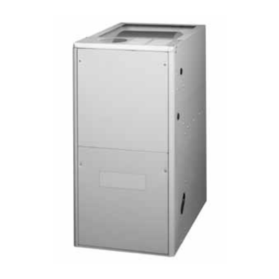
GAS FURNACES
USER'S MANUAl
NoN-CoNdENSiNG GAS FURNACES
80+ AFUE
*SA Upflow / Horizontal
Furnaces
*SK downflow
Furnaces
FiRE oR EXPloSioN HAZARd
• Failure to follow safety warnings exactly could
result in serious injury or property damage.
• Installation and service must be performed by
a qualified installer, service agency or the gas
supplier.
• Do not store or use gasoline or other flammable
vapors and liquids in the vicinity of this or any
other appliance.
do Not dEStRoY. PlEASE REAd CAREFUllY & KEEP iN A SAFE PlACE FoR FUtURE REFERENCE.
SiNGlE StAGE, two-StAGE, & ModUlAtiNG FURNACES
CoNdENSiNG GAS FURNACES
92.1% AFUE
*SC Upflow / Horizontal
Furnaces
*Sl downflow
Furnaces
wARNiNG
wHAt to do iF YoU SMEll GAS
• Do not try to light any appliance.
• Do not touch any electrical switch; do not use
any phone in your building.
• Leave the building immediately.
• Immediately call your gas supplier from a
neighbors phone. Follow the gas suppliers
instructions.
• If you cannot reach your gas supplier, call the
fire department.
95% - 97% AFUE
*Sd, *tC, *MQ Upflow /
Horizontal Furnaces
*SM & *tl downflow
Furnaces
Advertisement
Chapters
Table of Contents

Related Manuals for Nortek SA Series


Summary of Contents for Nortek SA Series
- Page 1 GAS FURNACES SiNGlE StAGE, two-StAGE, & ModUlAtiNG FURNACES USER’S MANUAl CoNdENSiNG GAS FURNACES NoN-CoNdENSiNG GAS FURNACES 80+ AFUE 92.1% AFUE 95% - 97% AFUE *SA Upflow / Horizontal *SC Upflow / Horizontal *Sd, *tC, *MQ Upflow / Furnaces Furnaces Horizontal Furnaces *SK downflow *Sl downflow *SM &...
-
Page 3: Table Of Contents
tABlE oF CoNtENtS iMPoRtANt SAFEtY iNFoRMAtioN ................... 4 GAS SUPPLY & PIPING ............................ 4 VENTING SYSTEM ............................4 CLEARANCES TO COMBUSTIBLES ........................ 5 SOURCES OF CORROSION ..........................5 FILTER ................................5 FLOOD DAMAGE ............................... 5 iMPoRtANt SAFEtY iNFoRMAtioN ................... 5 ABoUt tHE FURNACE ...................... -
Page 4: Important Safety Information
iMPoRtANt SAFEtY iNFoRMAtioN iMPoRtANt NotE Safety markings are used frequently throughout this If the gas supply fails to shut off or if overheating manual to designate a degree or level of seriousness and should not be ignored. wARNiNG indicates a potentially occurs, shut off the gas valve to the furnace before shutting off the electrical supply! hazardous situation that if not avoided, could result in... -
Page 5: Clearances To Combustibles
iMPoRtANt SAFEtY iNFoRMAtioN CAUtioN: SoURCES oF CoRRoSioN It is known that certain common household chemicals can This furnace requires unrestricted airflow for cause heat exchanger corrosion if the vapors are pulled into combustion and ventilation. For proper and the furnace’s burners The following is a list of chemicals safe operation, it is extremely important that the that should not be used or stored near the furnace. -
Page 6: About The Furnace
ABoUt tHE FURNACE iNtRodUCtioN FiltER Congratulations on the purchase on your new furnace! wARNiNG: With our dedication to quality, superior reliability, and outstanding warranty, we know you will be pleased with this new appliance. This furnace has been designed Never operate the furnace without a filter in place. and built to provide many years of safe and dependable Accumulating dust in the return air can build home comfort, providing it is properly installed and regular... -
Page 7: Component Locations For Non-Condensing Type Furnaces
CoMPoNENt loCAtioNS FoR NoN-CoNdENSiNG tYPE FURNACES Single Stage Models Main Air Blower Assembly Limit Switch (behind blower panel) Furnace Control Furnace Board Control Inducer Board Assembly Gas Valve Blower Pressure Transformer Door Switch Switch Transformer (behind blower panel) Flame Sensor Pressure Igniter Switch... -
Page 8: Component Locations For Condensing Type Furnaces
CoMPoNENt loCAtioNS FoR CoNdENSiNG tYPE FURNACES Single Stage Models Finish Finish Burner Flange Flange Igniter Assembly Roll-Out Blower Assembly Flame Switch Manifold (behind blower panel) Sensor Furnace Blower Door Control Furnace Switch Valve Board Control (behind blower panel) Board Inducer Main Air Limit Switch Transformer... - Page 9 Two-Stage Models Finish Finish Burner Flange Flange Assembly Flame Roll-Out Blower Assembly Furnace Sensor Switch (behind blower panel) Control Manifold Board Inducer Motor Choke Pressure Igniter Switches (C & D cabinets only) Motor Gas Valve Control Main Air Blower Board Limit Switch Furnace Door Switch...
-
Page 10: Startup & Shutdown
StARtUP & SHUtdowN StARtiNG tHE FURNACE 1. Make sure the filter is clean and in place. 2. Make sure the vent system is properly installed. 3. Set the thermostat to the lowest setting. 4. Close the manual gas valve outside the furnace. 5. -
Page 11: Maintenance & Inspection
MAiNtENANCE & iNSPECtioN FURNACE & AiR dUCtS BlowER & FiltER • The furnace should be inspected annually by a licensed • It is recommended that the blower compartment be HVAC technician. Table 1 below contains suggested cleaned of dirt or lint that may have accumulated in the inspections and frequency of maintenance. - Page 13 GÉNÉRAtEURS d’AiR CHAUd AU GAZ GÉNÉRAtEURS d’AiR CHAUd MoNo-ÉtAGE, à dEUX ÉtAGES Et ModUlANtS GUidE d’UtiliSAtioN GÉNÉRAtEURS d’AiR CHAUd AU GAZ GÉNÉRAtEURS d’AiR CHAUd AU GAZ à CoNdENSAtioN SANS CoNdENSAtioN AFUE de 80+ AFUE de 92,1 % AFUE de 95 % - 97 % Générateurs d’air chaud à...
- Page 15 tABlE dES MAtiÈRES RENSEiGNEMENtS iMPoRtANtS SUR lA SÉCURitÉ ............4 ALIMENTATION EN GAZ ET TUYAUTERIE ....................... 4 SYSTÈME DE VENTILATION ..........................4 DÉGAGEMENT AUX MATÉRIAUX COMBUSTIBLES ..................5 SOURCES DE CORROSION ..........................5 FILTRE ................................5 DOMMAGES CAUSÉS PAR UNE INONDATION ....................5 RENSEiGNEMENtS iMPoRtANtS SUR lA SÉCURitÉ...
-
Page 16: Renseignements Importants Sur La Sécurité
RENSEiGNEMENtS iMPoRtANtS SUR lA SÉCURitÉ Des symboles de sécurité sont fréquemment utilisés dans REMARQUE iMPoRtANtE : l’ensemble de ce manuel pour désigner un degré ou un niveau Si l’alimentation en gaz ne se coupe pas ou s’il y a surchauffe, de gravité... -
Page 17: Dégagement Aux Matériaux Combustibles
RENSEiGNEMENtS iMPoRtANtS SUR lA SÉCURitÉ MiSE EN GARdE : SoURCES dE CoRRoSioN Ce générateur d’air chaud requiert une circulation d’air Certains produits chimiques domestiques courants sont reconnus pour causer la corrosion de l’échangeur de chaleur lorsque les non restreinte pour la combustion et la ventilation. vapeurs sont aspirées dans les brûleurs du générateur d’air Pour un fonctionnement approprié... -
Page 18: À Propos Du Générateur D'air Chaud
à PRoPoS dU GÉNÉRAtEUR d’AiR CHAUd iNtRodUCtioN condensat gèle dans les conduites, le contacteur d’écoulement de condensat arrête le générateur d’air chaud. Seul un Nous vous félicitons pour l’achat de ce nouveau générateur technicien en CVC agréé peut réenclencher ce contacteur. d’air chaud! Fort de notre engagement envers la qualité, la fiabilité... -
Page 19: Emplacement Des Composants Pour Générateurs D'air Chaud Sans Condensation
EMPlACEMENt dES CoMPoSANtS PoUR GÉNÉRAtEURS d’AiR CHAUd SANS CoNdENSAtioN Modèles mono-étage Commutateur de sécurité Ensemble souffleur d’air principal Tableau de (derrière le panneau de souffleur) commande de générateur Tableau de d’air chaud commande de Ensemble générateur inducteur Robinet de gaz d’air chaud Commutateur Pressostat... -
Page 20: Emplacement Des Composants Pour Générateurs D'air Chaud À Condensation
EMPlACEMENt dES CoMPoSANtS PoUR GÉNÉRAtEURS d’AiR CHAUd à CoNdENSAtioN Modèles mono-étage Bride de Bride de Ensemble finition finition Allumeur brûleur Collecteur Ensemble souffleur Commutateur (derrière le panneau de souffleur) Détecteur de gaz de retour de flamme Tableau de Tableau de commande de Commutateur de commande de... - Page 21 Modèles à deux étages Bride de Bride de Ensemble finition finition brûleur Détecteur Ensemble souffleur Commutateur Tableau de commande de flamme Collecteur (derrière le panneau de souffleur) de retour de générateur de gaz d’air chaud Pressostat Étrangleur de moteur Allumeur d’inducteur (armoires C et D seulement) Tableau de...
-
Page 22: Démarrage Et Arrêt
dÉMARRAGE Et ARRÊt dÉMARRAGE dU GÉNÉRAtEUR d’AiR CHAUd S’assurer que le filtre est propre et en place. S’assurer que le système de ventilation est installé correctement. Régler le thermostat au réglage le plus bas. Fermer le robinet de gaz manuel à l’extérieur du générateur d’air chaud. -
Page 23: Entretien Et Inspection
ENtREtiEN Et iNSPECtioN GÉNÉRAtEUR d’AiR CHAUd Et SoUFFlEUR Et FiltRE CoNdUitS d’AiR • Il est recommandé d’éliminer la poussière et la mousse accumulées dans le compartiment de souffleur ou sur le • Il faut faire inspecter annuellement le générateur d’air chaud par souffleur et le moteur dans le cadre de l’inspection annuelle. - Page 24 O’Fallon, MO, © Nortek Global HVAC LLC 2015. All Rights Reserved. Spécifications et illustrations sujettes à changements sans préavis ou sans aucune obligation. 708967B (Replaces 708967A) (07/15) O’Fallon, MO, © Nortek Global HVAC LLC 2015. Tous Droits Réservés. 708967B (Remplace 708967A)
Need help?
Do you have a question about the SA Series and is the answer not in the manual?
Questions and answers