Table of Contents
Advertisement
Quick Links
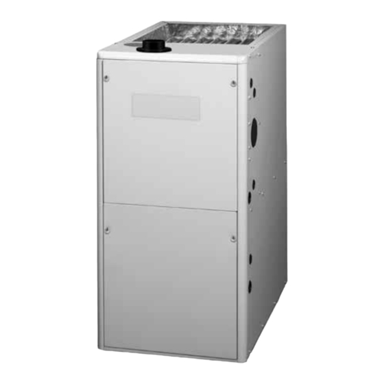
*SD Ultra Low Nox Series Single Stage, Condensing Gas Furnace
INSTALLATION INSTRUCTIONS
This product complies with SJVAPCD 4905 and SCAQMD 1111 with NOx levels below 14 ng/J when operated on natural gas.
• Failure to follow safety warnings exactly could result in serious injury, death or property
damage.
• Installation and service must be performed by a qualified installer, service agency or the gas
supplier.
• Do not store or use gasoline or other flammable vapors and liquids in the vicinity of this or
any other appliance.
• Do not try to light any appliance.
• Do not touch any electrical switch; do not use any phone in your building.
• Leave the building immediately.
• Immediately call your gas supplier from a neighbors phone. Follow the gas suppliers instructions.
• If you cannot reach your gas supplier, call the fire department.
DO NOT DESTROY. PLEASE READ CAREFULLY & KEEP IN A SAFE PLACE FOR FUTURE REFERENCE.
*SD Upflow / Horizontal Furnace
WARNING
FIRE OR EXPLOSION HAZARD
WHAT TO DO IF YOU SMELL GAS
95.0% AFUE
Advertisement
Table of Contents

Related Manuals for Nortek L9X1


Summary of Contents for Nortek L9X1
- Page 1 *SD Ultra Low Nox Series Single Stage, Condensing Gas Furnace 95.0% AFUE INSTALLATION INSTRUCTIONS *SD Upflow / Horizontal Furnace This product complies with SJVAPCD 4905 and SCAQMD 1111 with NOx levels below 14 ng/J when operated on natural gas. WARNING FIRE OR EXPLOSION HAZARD •...
-
Page 2: Table Of Contents
TABLE OF CONTENTS IMPORTANT SAFETY INFORMATION ......3 GAS SUPPLY & PIPING ..........17 Leak Check ..............18 REQUIREMENTS & CODES ..........3 Main Burner Gas Orifice ........... 19 Combustion Air Quality ............. 4 Air Inlet Orifice ..............19 Heating Load ..............4 ELECTRICAL WIRING ...........19 Installation in a Garage ............ -
Page 3: Important Safety Information
FIGURES & TABLES ............31 WARNING: Figure 23. *SD Cabinet Dimensions ......31 Airflow Data Improper installation, service, adjustment, or Table 7. *SD 050U-T23A* Blower Data maintenance may cause explosion, fire, electrical (Heating Airflow) ..........32 shock or other hazardous conditions which may Table 8. -
Page 4: Combustion Air Quality
current revision of the National Fuel Gas Code (NFPA54/ Safety • US: (NFGC) NFPA 54–1999/ANSI Z223.1 and the Installation ANSI Z223.1). Standards, Warm Air Heating and Air Conditioning Systems • Use only with type of gas approved for this furnace. Refer ANSI/NFPA 90B. -
Page 5: Installation In A Garage
Installation in a Garage COMBUSTION AIR & VENTING REQUIREMENTS WARNING: WARNING: Do not place combustible material on or against the furnace cabinet or within 6 inches of the CARBON MONOXIDE POISONING HAZARD vent pipe. Do not place combustible materials, Failure to follow the steps outlined below including gasoline or any other flammable vapors for each appliance connected to the venting and liquids, in the vicinity of the furnace. -
Page 6: Direct Vent Furnaces
IMPORTANT INFORMATION: CAUTION: • This furnace must be vented in compliance with the current revision of the National Fuel Gas Code Exhaust fans, clothes dryers, fireplaces and (ANSI-Z223.1/NFPA54). Instructions for determining the adequacy of an installation can be found in the current other appliances that force air from the house revision of the NFGC (ANSI Z223.1 / NFPA54). -
Page 7: Outdoor Air From A Crawl Space Or Vented Attic
Outdoor Air Using Vertical Ducts EXAMPLE If combustion air is taken from outdoors through vertical If the combined input rate of all appliances is less than or ducts, the openings and ducts must have a minimum free equal to 100,000 Btuh, each opening must have a free area of one square inch per 4,000 Btuh of total appliance area of at least 100 in . -
Page 8: Air Directly Through An Exterior Wall
Air Directly Through An Exterior Wall Conventional Vent Systems - Unconfined Spaces If combustion air is provided directly through an exterior An unconfined space is an area including all rooms not separated by doors with a volume greater than 50 cubic feet wall, the two openings must each have free area of at least one square inch per 4,000 Btuh of total appliance input. -
Page 9: Vent Pipe Length & Diameter
Vent Pipe Installation MATERIALS STANDARDS Schedule 40PVC ............D1785 CAUTION: CPVC ................D1784 PVC-DWV ..............D2665 Combustion air must not be drawn from a SDR-21 & SDR-26 ............D2241 corrosive atmosphere. ABS-DWV ..............D2661 Schedule 40 ABS .............F628 Foam / Cellular Core PVC ........F891 This furnace has been certified for installation with zero *PolyPro by DuraVent ..........ULC-S636 ®... -
Page 10: Outdoor Terminations - Horizontal Venting
1. Slide the rubber coupling over the end of the pipe that is attached to the furnace and secure it with one of the hose clamps. 2. Slide the other end of the rubber coupling onto the other pipe from the vent. 3. -
Page 11: Vent Freezing Protection
Plumbing Vent Roof Boot MAXIMUM FLUE PIPE LENGTH (FEET) WINTER DESIGN IN UNCONDITIONED & EXTERIOR SPACES (Both Pipes) Elbows on the combustion air TEMPERATURE WITHOUT INSULATION WITH INSULATION* inlet must be positioned pointing away from the exhaust vent. 12” Above Maximum Expected Snow Level (Both pipes) *NOTE: Insulation thickness greater than 3/8 inch, based on an R value... -
Page 12: Circulating Air Requirements
CIRCULATING AIR REQUIREMENTS • If a cooling system is installed in parallel with the furnace, a damper must be installed to prevent chilled air from entering the furnace and condensing on the heat WARNING: exchanger. If a manually operated damper is installed, it must be designed so that operation of the furnace is Do not allow combustion products to enter the prevented when the damper is in the cooling position and... -
Page 13: Acoustical Treatments
with wide duct pliers. See for furnace flange Horizontal Furnaces Figure 23 locations. NOTE: If system installation includes AC coil WARNING: casing, bend the flanges on the coil casing upward 90° before attaching the supply air duct. • Position the supply air ductwork onto the furnace ensuring The furnace must not be installed directly on even alignment of furnace air opening and supply air carpeting, tile, or any combustible material other... -
Page 14: Inducer & Venting Options
Inducer Assembly Rotation WARNING: Inducer rotation must be completed before the furnace is connected to gas and electric. If Nuts (x2) both utilities have been connected, follow the shutdown procedures printed on the furnace Bolt Washer label and disconnect the electrical supply. Lockwasher Nuts (x2) CAUTION:... -
Page 15: Accessories
Accessories Typical Orientation The components below are included in the extra parts bag 1. Install the PVC Tee vertically on the 2” vent pipe that is that is supplied with the purchase of your furnace. Depending extending out the side of the cabinet. Permanently bond on your particular installation, some of these components are them together using appropriate primer and cement. -
Page 16: Alternate Orientation
Optional PVC Pipe Installation INSTALLATION OF PVC COMPONENTS When running the 2” PVC pipe out through the top of the (TYPICAL ORIENTATION) furnace, there may be possible clearance issues when transitioning the PVC pipe from 2” to 3”: 2” PVC Pipe from Inline •... -
Page 17: Bottom Panel Removal
GAS SUPPLY & PIPING EXCEPTIONS & CLARIFICATIONS TO THE GENERAL RULES: WARNING: • If the vent exits the furnace horizontally, the vent may be turned vertically with a tee. The drip leg formed by the tee must include a drain. (Option 2, Option 3, Option 5, FIRE OR EXPLOSION HAZARD Option 6, Option 8, Option 9, Option 12, Option 13. -
Page 18: Leak Check
Leak Check WARNING: WARNING: THE FURNACE IS EQUIPPED TO RUN ON NATURAL GAS ONLY. AN LP/PROPANE FIRE OR EXPLOSION HAZARD CONVERSION KIT IS NOT AVAILABLE. USE Failure to follow safety warnings exactly could OF LP/PROPANE WITH THIS FURNACE CAN result in serious injury, death or property CAUSE FIRE, EXPLOSION, PROPERTY DAMAGE, damage. -
Page 19: Main Burner Gas Orifice
Main Burner Gas Orifice IMPORTANT NOTES: 1. To remove the main burner gas orifice shut off the main An electrical disconnect must be installed readily power and gas supply to the furnace. accessible from and located within sight of the furnace. or the 2. -
Page 20: Start-Up & Adjustments
FURNACE FURNACE CABINET NOMINAL MAXIMUM MINIMUM MAXIMUM MAXIMUM MODEL INPUT WIDTH ELECTRICAL OPERATING OPERATING FURNACE FUSE OR CIRCUIT NUMBER (BTUH) (IN.) SUPPLY VOLTAGE VOLTAGE AMPERES BREAKER AMPS* *SD-050U-T23A 50,000 14 ¼ 120-60-1 *SD-100U-T35C 100,000 120-60-1 12.5 * Time-delay fuses or circuit breakers are required. RECOMMENDED THERMOSTAT WIRE LENGTH THERMOSTAT WIRE GAUGE 2 - WIRE - HEATING... -
Page 21: Verifying & Adjusting Input Rate
Verifying & Adjusting Input Rate Capscrew The input rate must be verified for each installation to prevent over-firing of the furnace. NOTE: The input rate must not exceed the rate shown on the furnace rating plate. To determine the exact input rate, perform the following procedures: 1. -
Page 22: Control Board Functions
CONTROL BOARD FUNCTIONS If an alarm is detected, the error coded is displayed starting with “E” followed with the two digit error code. For instance Control Interface “E3.4” would correspond to Pressure switch #2 opening System Reset: during the heat cycle. •... -
Page 23: Cooling Off Delay(Cod)
• OdU (Outdoor Unit) is the cooling mode. While OdU is on • Press the MENU button, the control will show the options the LED Display, press the OPTION button to go into the on the display. Keep pressing the MENU button, the cooling menu. -
Page 24: Cooling Or Heat Pump Mode
OPERATING SEQUENCE gas flame has proven, the blower motor will slowly ramp up to the selected motor torque. The blower will continue The operating sequences for the heating, cooling, and fan to operate after the call for heat has been removed for 100 modes are described below. -
Page 25: Cooling Cycle
Retry 1st Stage Cooling If the first ignition attempt fails during a normal heat cycle 1. When Y1 and G are detected simultaneously, the control sequence, the control will perform retry as follows: will energize the blower with 1st stage cooling airflow and 1. -
Page 26: Troubleshooting
Air Filter(s) - Air filter(s) are not supplied with the furnace as WARNING: shipped from the factory. The installer must provide a high velocity filter that is appropriately sized to the return air duct Holes in the vent pipe or heat exchanger can opening or external filter rack. - Page 27 *SD FAULT CODES AND TROUBLESHOOTING GUIDE ALARM ALARM BOARD TROUBLESHOOTING DESCRIPTION EXPLANATION DISPLAY 1. Check for low input voltage. Internal Voltage Frequency is out of range. The control Frequency out 2. Powering the furnace with generator could Failure board monitors the voltage frequency and will of Range cause this error.
- Page 28 *SD FAULT CODES AND TROUBLESHOOTING GUIDE ALARM ALARM BOARD TROUBLESHOOTING DESCRIPTION EXPLANATION DISPLAY All pressure switches are checked at the Pressure Switch #2 beginning of the heat cycle to be open. If the or collector switch Both inducer and collector switches are shorted E3.3 control detects the inducer pressure switch #2 or closed at intitial...
- Page 29 *SD FAULT CODES AND TROUBLESHOOTING GUIDE ALARM ALARM BOARD TROUBLESHOOTING DESCRIPTION EXPLANATION DISPLAY Damaged open ignitor or internal control relay. 1. Check wiring, verify the ignitor is connected. 2. Watch through sight glass to see if it glows Controls senses if the ignitor is open.Measure Igniter during ingnition.
-
Page 30: Furnace Components
FURNACE COMPONENTS The descriptions below are various functional components Gas Valve: Controls the flow of gas to the burners. When the that affect the operation and shutting down of this furnace. gas valve is energized it automatically opens and regulates Some of these components and their locations are shown in the gas pressure in the manifold. -
Page 31: Figures & Tables
FIGURES & TABLES TOP VIEW BOTTOM VIEW *SD UPFLOW / HORIZONTAL FURNACES Front Brace MODEL # DIM. -A- DIM. -B- DIM. -C- 050U-T23A 14 1/4 12 5/8 12 7/8 Bottom Panel 100U-T35C 19 3/8 19 5/8 NOTE: Dimensions shown in inches. 3 1/4 Combustion Air T-stat... - Page 32 Airflow Data HEATING AIRFLOW (CFM) & TEMPERATURE RISE (°F) EXTERNAL STATIC PRESSURE (IN. W.C.) MODEL NAME/ RETURN MOTOR HEATING INPUT AIR VIA: SPEED RISE RISE RISE RISE RISE Tap 9 Tap 8 Tap 7 Tap 6 Tap 5 Bottom Tap 4 Tap 3 Tap 2 -050U-T23A*...
-
Page 33: (Cooling Airflow)
COOLING AIRFLOW (CFM) EXTERNAL STATIC PRESSURE (IN. W.C.) MODEL NAME RETURN MOTOR HEATING INPUT AIR VIA: SPEED (CFM) (CFM) (CFM) (CFM) (CFM) (CFM) (CFM) (CFM) Tap 9 1,420 1,395 1,360 1,330 1,300 1,280 1,245 1,220 Tap 8 1,310 1,270 1,245 1,215 1,180 1,145... - Page 34 HEATING AIRFLOW (CFM) & TEMPERATURE RISE (°F) EXTERNAL STATIC PRESSURE (IN. W.C.) RETURN MOTOR MODEL NUMBER/ SPEED HEATING INPUT VIA: RISE RISE RISE RISE RISE 1,850 1,790 1,745 1,700 1,650 Bottom 5 ** 1,745 1,690 1,645 1,590 1,535 Only 1,480 1,420 1,360 1 ***...
-
Page 35: (Cooling Airflow)
COOLING AIRFLOW (CFM) EXTERNAL STATIC PRESSURE (IN. W.C.) MOTOR MODEL NAME/ RETURN SPEED HEATING INPUT AIR VIA: 2,250 2,250 2,190 2,130 2,080 2,025 1,975 1,915 2,055 2,010 1,970 1,900 1,840 1,790 1,730 1,675 1,900 1,845 1,795 1,750 1,700 1,650 1,575 1,520 1,850 1,790... -
Page 36: Electrical Information
Electrical Information Figure 24. *SD Wiring Diagram... - Page 37 LADDER DIAGRAM Single Stage Furnace DOOR SWITCH BLOWER MOTOR FLAME SENSOR EAC 1 ELECTRONIC EAC 2 AIR CLEANER HUM 1 HUMIDIFIER HUM 2 INDUCER IGN-H IGNITOR IGN-N TRANSFORMER PRESSURE TRANSDUCER VALVE INDUCER LIMIT TWIN MAIN AIR BLOWER BLOWER LIMIT LIMIT LIMIT INDUCER PRESSURE...
-
Page 38: Gas Information
Gas Information GAS FLOW RATES GAS FLOW RATES (CUBIC FEET PER HOUR) (CUBIC FEET PER HOUR) CUBIC FEET PER CUBIC FEET PER TIME FOR TIME FOR REVOLUTION OF GAS METER REVOLUTION OF GAS METER ONE REVOLUTION ONE REVOLUTION (SECONDS) (SECONDS) 1,800 3,600 1,500... -
Page 39: Venting Information
Venting Information VENT TERMINAL AIR SUPPLY INLET AREA WHERE TERMINAL IS NOT PERMITTED US Installations CLEARANCE LOCATION Direct Vent Conventional Vent (2-pipe) Furnaces (1-pipe) Furnaces Clearance above grade, veranda, porch, deck, 12 inches (30cm) 12 inches (30cm) balcony, or maximum expected snow level. 6 inches (15cm) for appliances <... - Page 40 HORIZONTAL VENTING w/ 2-Pipes Straps or other suitable supports Wall (Upflow Furnace Shown) at minimum 5 ft. intervals (both pipes) Seal / caulk around pipes First support as close at wall to furnace as possible 90° Elbows 90° Elbow COMBUSTION AIR VENT PIPE Flue Pipe must slope FLUE PIPE upward 1/4”...
- Page 41 *SD SERIES UPFLOW - 1 PIPE OPTIONS Rubber COMBUSTION COMBUSTION Grommet COMBUSTION Plug Plug NOTE 5 NOTE 5 Rubber Grommet OPTION 1 OPTION 2 OPTION 3 Rubber Grommet PVC Trap See VIEW C for drain line positions See VIEW A for drain line positions See VIEW B for drain line positions VIEW -A- VIEW -B-...
- Page 42 *SD SERIES HORIZONTAL RIGHT - 1 PIPE OPTIONS Rubber See VIEW D for See VIEW E for Grommet Plug drain line positions drain line positions NOTE 5 Plug COMBUSTION OPTION OPTION COMBUSTION Plug Plug VIEW -D- VIEW -E- VIEW -G- VIEW -F- Inline Drain Field Supplied...
- Page 43 *SD SERIES HORIZONTAL RIGHT - 2 PIPE OPTIONS Rubber See VIEW H for See VIEW I for Grommet Plug drain line positions drain line positions NOTE 5 Plug COMBUSTION AIR COMBUSTION AIR OPTION OPTION Flange Plug Plug VIEW -H- VIEW -I- VIEW -J- VIEW -K- Inline Drain...
- Page 44 PRESSURE SWITCH TUBING FOR A50 FURNACES Upflow Installation Upflow Installation Upflow Installation Inducer Rotated Left Inducer Rotated Right Inducer Vertical Alternate Location Horizontal Left Installation Horizontal Right Installation Inducer Vertical Inducer Vertical Alternate Alternate Location Location Horizontal Right Installation Horizontal Left Installation Inducer Rotated Right Inducer Rotated Left Alternate...
- Page 45 PRESSURE SWITCH TUBING FOR C100 FURNACES Upflow Installation Upflow Installation Upflow Installation Inducer Rotated Left Inducer Vertical Inducer Rotated Right Alternate Alternate Alternate Alternate Locations Locations Locations Locations Horizontal Left Installation Horizontal Right Installation Inducer Vertical Inducer Vertical Alternate Locations Horizontal Right Installation Horizontal Left Installation Inducer Rotated Right...
-
Page 48: Installation Checklist
G A S - F I R E D L I S T E D Specifications & illustrations subject to change without notice or incurring obligations (01/21). 10361320 O’Fallon, MO, © Nortek Global HVAC LLC 2021. All Rights Reserved. (Replaces 1032111A)
Need help?
Do you have a question about the L9X1 and is the answer not in the manual?
Questions and answers