Table of Contents
Advertisement
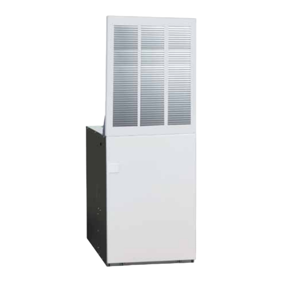
E4 Series Electric Furnace
OWNER'S MANUAL & INSTALLATION INSTRUCTIONS
Downflow & Upflow Models
ELECTRICAL SHOCK, FIRE OR
EXPLOSION HAZARD
Failure to follow safety warnings
exactly could result in serious injury
or property damage.
Improper servicing could result
in dangerous operation, serious
injury, death or property damage.
• Before servicing, disconnect all
electrical power to furnace.
• When servicing controls, label
all wires prior to disconnecting.
Reconnect wires correctly.
• Verify proper operation after
servicing.
DO NOT DESTROY. PLEASE READ CAREFULLY & KEEP IN A SAFE PLACE FOR FUTURE REFERENCE.
WARNING / AVERTISSEMENT
Le non-respect des avertissements de sécurité pourrait
entraîner un fonctionnement dangereux de l'appareil, des
blessures graves, la mort ou des dommages matériels.
Un entretein incorrect pourrait entraîner un fonctionnement
dangereux de l'appareil, des blessures graves, la mort ou
des dommages matériels.
• Couper toute alimentation électrique au générateur d'air
chaud avant de prodéder aux travaux d'entretein.
• Au moment de l'entretien des commandes, étiquetez
tous les fils avant de les débrancher. S'assurer de les
raccorder correctement.
• S'assurer que l'appareil fonctionne adéquatement aprés
l'entretien.
RISQUE DE CHOC ÉLECTRIQUE,
D'INCENDIE OU D'EXPLOSION
Advertisement
Table of Contents

Related Manuals for Nortek E4 Series


Summary of Contents for Nortek E4 Series
- Page 1 E4 Series Electric Furnace OWNER’S MANUAL & INSTALLATION INSTRUCTIONS Downflow & Upflow Models WARNING / AVERTISSEMENT ELECTRICAL SHOCK, FIRE OR RISQUE DE CHOC ÉLECTRIQUE, EXPLOSION HAZARD D’INCENDIE OU D’EXPLOSION Failure to follow safety warnings Le non-respect des avertissements de sécurité pourrait exactly could result in serious injury entraîner un fonctionnement dangereux de l’appareil, des...
-
Page 2: Table Of Contents
TABLE OF CONTENTS USER INFORMATION IMPORTANT SAFETY INFORMATION ....3 UNIT MAINTENANCE ..........4 Furnace Filter ..............4 OPERATING INSTRUCTIONS ........3 Coil Filters ................4 Cooling Operation............3 Blower Compartment ............4 Heating Operation ............3 TrOuBLEShOOTiNg ..........4 Operating the Indoor Blower Continuously .....3 Turning the Heater OFF ...........3 INSTALLER INFORMATION Alcove Installation ............11... -
Page 3: Important Safety Information
USER INFORMATION IMPORTANT SAFETY INFORMATION OPERATING INSTRUCTIONS Safety markings are used to designate a degree or level NOTE: Thermostat styles vary. Some models may not of seriousness and should not be ignored. WARNING include the AUTO mode and others will have the AUTO indicates a potentially hazardous situation that if not in place of the HEAT and COOL. -
Page 4: Unit Maintenance
USER INFORMATION Furnace Filter WARNING: Never operate the furnace without a filter in place. Accumulating dust in the return air can build up on internal components, resulting in loss of efficiency, equipment damage, and possible fire. • E4 furnaces are supplied with a single air filter when shipped from the factory. -
Page 5: Important Safety Information
INSTALLER INFORMATION IMPORTANT SAFETY INFORMATION ALL MODELS CLOSET ALCOVE INSTALLER: Please read all instructions before servicing 6" 18" ront this equipment. Pay attention to all safety warnings and 0" 0" any other special notes highlighted in the manual. Safety 0" 0"... -
Page 6: Circulating Air Requirements
CIRCULATING AIR REQUIREMENTS Return Air Connections Air return to the furnace must have a minimum free area WARNING: opening. See Table 1 (page 5). A return air grille for closet or alcove installations is available. Acceptable closet installations with return air entering through an All return ducts must be secured to the furnace opening in the floor or ceiling of a closet, must meet all with sheet metal screws. -
Page 7: Unconditioned Spaces
Unconditioned Spaces Frame All duct work passing through unconditioned space must be properly insulated to minimize duct losses and prevent Fasteners (4) condensation. Use insulation with an outer vapor barrier. Refer to local codes for insulation material requirements Top of Furnace Closed-Off Spaces Living space not served by, and closed off from the return air... -
Page 8: Optional Equipment
FURNACE INSTALLATION NOTE: Since all installations are different, the sequence of 24 3/4” (628 mm) these steps may differ from the actual installation. These installation procedures are suggested for typical furnace installations. Only qualified hVAC technicians should install this furnace. General Information 20”... -
Page 9: Locating & Cutting Floor Openings
REAR WALL OF CLOSET OR ALCOVE REAR WALL OF CLOSET OR ALCOVE 1 3/4" MIN. 2 3/8" MIN. FLOOR CUT-OUT FLOOR CUT-OUT 14 1/2” X 14 1/2” 17 1/2” X 14” FOR DOWNFLOW FOR UPFLOW FURNACES WITH FURNACES WITH STD. DUCT STD. -
Page 10: Standard Duct Connector Installation
NOTE: Requirements for sealing ductwork vary DUCT CONNECTOR from region to region. Consult with local codes for IF FLOOR CAVITY TYpE & pArT NuMBEr requirements specific to your area. “X” IS: STANDARD DUCT SCREW DOWN 7/8” / (22) 901987A 904008 2”... -
Page 11: Round Duct Connector Installation
STAPLES OR SHEET DUCT CONNECTOR TABS METAL SCREWS Wall Return Air Grille Coil Air NARROW DUCT NARROW Filters DUCT DUCT FLAP 27" (686 mm) DUCT 56" (1423 mm) CONNECTOR SHEET METAL A/C or H/P SCREWS Coil NARROW DUCT 29" Furnace ( 737 mm) 24 3/4"... -
Page 12: Upflow Furnaces
Upflow Furnaces equivalent method of securing the rear of the unit may be used as long as it prevents displacement during The following steps describe installation instructions for transport if used in a manufactured home. an overhead supply duct system with a return air system that can be either over the floor (unducted) or through NOTE: The furnace does not need to be positoned the floor (ducted). -
Page 13: Through-The-Floor Return Air System (Ducted)
ELECTRICAL WIRING Upflow Duct Connector WARNING: ELECTRICAL SHOCK, FIRE OR Furnace EXPLOSION HAZARD Failure to follow safety warnings exactly could result in serious injury or property damage. Improper servicing could result in dangerous operation, serious injury, death or property damage. Filter (one obtained •... -
Page 14: Connecting Supply Service Wires
Remove cover from single-circuit kit (if supplied). on the heating mode indoor blower configuration. c. Insert metal buss bars of kit into lugs of circuit • The E4 series electric furnaces incorporate an breaker. integrated control. The thermostat’s 1st stage d. -
Page 15: Selecting Blower Speed
Blower installation PLUG / RECEPTACLE 1. Turn off all electrical supply circuits to the furnace at POSITION the main service panel. Low Med-LO Med-Hi High peed lower 2. Remove furnace front door and switch furnace circuit Yellow Blue Black ontrol lower breaker(s) to OFF. -
Page 16: Figures & Tables
FigurES & TABLES 5 Ton Blower Figure 19. E4 Furnace Components... - Page 17 13 1/2” 17” VIEW VentilAire Knockout VentilAire Knockout (1 1/2” X 5”) (1 1/8” X 4 1/2”) T-Stat (Ø 5/8”) 20” 24 1/2” T-Stat RIGHT LEFT FRONT (Ø 5/8”) SIDE SIDE VIEW Electric Ø 1 1/8” 29” Ø 2” Ø 7/8” 2 1/4”...
-
Page 18: Electrical Data
Electrical Data 5-WIRE THERMOSTAT 4-WIRE THERMOSTAT WIRE WIRE NUTS NUTS TO E4EB FURNACE CONTROL WIRING TO E4EB FURNACE CONTROL WIRING HEAT PUMP THERMOSTAT 2-WIRE THERMOSTAT UNSTRIPPED WIRES WIRE WIRE NUTS NUTS TO E4EB FURNACE CONTROL WIRING TO E4EB FURNACE CONTROL WIRING Figure 22. - Page 19 MAXIMUM MODEL MINIMUM LOW VOLTAGE SUPPLY TOTAL OVER- NuMBEr CIRCUIT THERMOSTAT CIRCUIT AMPERES CURRENT E4EB- AMPACITY WIRE SIZE RATING 010H Single 44.6 Single 51.2 012H 2-Wire system Dual "A" 27.1 maximum wire lengths: Dual "B" 24.2 24 Ga. = 55' 22 Ga.
-
Page 20: Wiring Diagrams
Wiring Diagrams Figure 23. E4EB-010h Models... - Page 21 Figure 24. E4EB-012h Models...
- Page 22 Figure 25. E4EB-015h & E4EB-017h Models...
- Page 23 Figure 26. E4EB-020h & E4EB-023h Models...
-
Page 24: Installation / Performance Check List
INSTALLATION / PERFORMANCE CHECK LIST ELECTRICAL SYSTEM INSTALLER NAME: lectrical connectionS tigHt ine Voltage polarity correct city: State: Supply Voltage: ..............VOLTS INSTALLATION ADDRESS: aS tHe tHermoStat Been caliBrated S tHe tHermoStat leVel city: State: S tHe Furnace grounded properly S tHe Heat anticipator Setting correct unit model # COMBuSTiON Air &...
Need help?
Do you have a question about the E4 Series and is the answer not in the manual?
Questions and answers