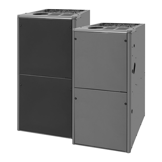
Nortek VG7TC-FS User Manual
Single stage & two-stage gas furnaces
Hide thumbs
Also See for VG7TC-FS:
- Installation instructions manual (44 pages) ,
- Installation instructions manual (44 pages) ,
- Installation instructions manual (112 pages)
Table of Contents
Advertisement
SINGLE STAGE & TWO-STAGE GAS FURNACES
USER'S MANUAL
NON-CONDENSING GAS
FURNACES
(US ONLY)
*SA Upflow / Horizontal
Furnaces
*SK Downflow Furnaces
FIRE OR EXPLOSION HAZARD
• Failure to follow safety warnings exactly could
result in serious injury or property damage.
• Installation and service must be performed by
a qualified installer, service agency or the gas
supplier.
• Do not store or use gasoline or other flammable
vapors and liquids in the vicinity of this or any
other appliance.
DO NOT DESTROY. PLEASE READ CAREFULLY & KEEP IN A SAFE PLACE FOR FUTURE REFERENCE.
CONDENSING GAS FURNACES
*SC Upflow / Horizontal
Furnaces
WARNING
• Do not try to light any appliance.
• Do not touch any electrical switch; do not use
any phone in your building.
• Leave the building immediately.
• Immediately call your gas supplier from a
neighbors phone. Follow the gas suppliers
instructions.
• If you cannot reach your gas supplier, call the
fire department.
*SD & *TC
Upflow / Horizontal Furnaces
& *TE Furnaces (Dedicated Upflow only)
Downflow Furnaces
WHAT TO DO IF YOU SMELL GAS
*TN
Advertisement
Table of Contents

Subscribe to Our Youtube Channel
Summary of Contents for Nortek VG7TC-FS
- Page 1 SINGLE STAGE & TWO-STAGE GAS FURNACES USER’S MANUAL NON-CONDENSING GAS CONDENSING GAS FURNACES FURNACES (US ONLY) *SD & *TC *SA Upflow / Horizontal Upflow / Horizontal Furnaces Furnaces & *TE Furnaces (Dedicated Upflow only) *SC Upflow / Horizontal Furnaces *SK Downflow Furnaces Downflow Furnaces WARNING WHAT TO DO IF YOU SMELL GAS...
-
Page 3: Table Of Contents
TABLE OF CONTENTS IMPORTANT SAFETY INFORMATION ................... 4 GAS SUPPLY & PIPING ..............................4 FILTER ..................................4 FLOOD DAMAGE.................................4 VENTING SYSTEM ..............................5 SOURCES OF CORROSION ............................5 CLEARANCES TO COMBUSTIBLES ..........................5 IMPORTANT SAFETY INFORMATION ................... 5 ABOUT THE FURNACE ......................6 INTRODUCTION ................................6 CATEGORY I (NON-CONDENSING) FURNACES .................... -
Page 4: Important Safety Information
IMPORTANT SAFETY INFORMATION Safety markings are used frequently throughout this manual WARNING: to designate a degree or level of seriousness and should not be ignored. WARNING indicates a potentially hazardous The furnace was shipped from the factory equipped situation that if not avoided, could result in personal injury or to operate on natural gas. -
Page 5: Venting System
IMPORTANT SAFETY INFORMATION VENTING SYSTEM • Cleaning solvents (perchloroethylene) • Printing inks, paint removers, varnishes, etc. • Hydrochloric acid WARNING: • Cements and glues • Antistatic fabric softeners It is imperative to maintain proper operation of the • Masonry acid washing materials venting system, including the masonry chimney (if applicable). -
Page 6: About The Furnace
ABOUT THE FURNACE INTRODUCTION FILTER Congratulations on the purchase on your new furnace! WARNING: With our dedication to quality, superior reliability, and outstanding warranty, we know you will be pleased with this new appliance. This furnace has been designed and built to Never operate the furnace without a filter in place. -
Page 7: Component Locations For Non-Condensing Type Furnaces
COMPONENT LOCATIONS FOR NON-CONDENSING TYPE FURNACES Single Stage Models Main Air Blower Assembly Limit Switch (behind blower panel) Furnace Control Furnace Board Control Inducer Board Assembly Gas Valve Blower Pressure Transformer Door Switch Switch Transformer (behind blower panel) Flame Sensor Pressure Igniter Switch... -
Page 8: Component Locations For Condensing Type Furnaces
COMPONENT LOCATIONS FOR CONDENSING TYPE FURNACES Single Stage Models Finish Burner Flange Igniter Assembly Roll-Out Flame Switch Manifold Sensor Furnace Control Valve Board Inducer Main Air Limit Switch Limit Switch Inducer Condensate Assembly Pressure Switch (‘B’, ‘C’, & ‘D’ cabinets only) Inducer Pressure Switch Transformer... - Page 9 Two-Stage Models Finish Burner Flange Assembly Flame Roll-Out Sensor Switch Manifold Inducer Pressure Igniter Switches Gas Valve Main Air Limit Switch Furnace Control Board Inducer Limit Switch Condensate Pressure Inducer Switches Assembly Blower Door Transformer Switch Motor Control Motor Choke Board (C &...
-
Page 10: Startup & Shutdown
STARTUP & SHUTDOWN STARTING THE FURNACE Make sure the filter is clean and in place. Make sure the vent system is properly installed. Set the thermostat to the lowest setting. Close the manual gas valve outside the furnace. Turn off all electric to the furnace. Remove the door from the burner compartment. -
Page 11: Maintenance & Inspection
MAINTENANCE & INSPECTION FURNACE & AIR DUCTS BLOWER & FILTER • The furnace should be inspected annually by a licensed • It is recommended that the blower compartment be cleaned HVAC technician. Table 1 below contains suggested of dirt or lint that may have accumulated in the compartment inspections and frequency of maintenance. - Page 12 G A S - F I R E D L I S T E D Specifications & illustrations subject to change without notice or incurring obligations (05/23). 1034878A (Replaces 10348780) O’Fallon, MO, © Nortek Global HVAC LLC 2023. All Rights Reserved.


Need help?
Do you have a question about the VG7TC-FS and is the answer not in the manual?
Questions and answers