
Related Manuals for REMKO RVT 261DC


Summary of Contents for REMKO RVT 261DC
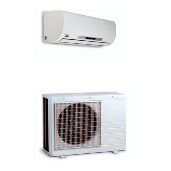
- Page 1 REMKO RVT RVT 261DC, RVT 351DC, RVT 521DC Inverter wall - room air conditioner in split design Operation · Technology · Spare parts Edition GB – T10...
-
Page 3: Table Of Contents
/ operation of the equipment! These instructions are part of the equipment and must always be kept in the vicinity of the installation or on the equipment Made by REMKO Subject to modifications; No liability accepted for errors or misprints! -
Page 4: Safety Notes
REMKO GmbH supplied by REMKO as this may maintenance work or cleaning & Co. KG. cause malfunctions. the equipment. The warranty conditions are listed in the "General business and... -
Page 5: Transport And Packaging
Liquefier Filter dryer Capillary tube flow regulator The RVT 261-521DC room air conditioning units have a REMKO RVT...AT outdoor component as Schematic of refrigerant circuit in indoor unit - cooling well as an indoor unit RVT...IT. The outdoor component serves to... -
Page 6: Operation
REMKO RVT...DC Operation The indoor unit is easy to operate using an infrared remote control. This is supplied as standard. The indoor unit beeps to acknowledge the correct transmission of data. If it is not possible to program the indoor unit using the remote control, it can also be manually operated. - Page 7 Buttons on the remote control Buttons on the remote control "FAN" button Press this button to set the "ON/OFF" Button required fan speed. Press this button to start the 4 settings are available: unit. automatic, high, medium and low fan speed. "MODE"...
- Page 8 REMKO RVT...DC Button functions A symbol is shown on the display to indicate that the settings are being transferred. By pressing the ON / OFF button, you can activate or deactivate your ON/OFF Button unit. The programmed settings and adjustment values before the unit was turned off will appear on the display.
- Page 9 In cooling mode, the air in the room is cooled down to the set target COOLING Mode temperature. The desired room temperature is set with the ▲/▼buttons in 1 °C increments. If the room temperature is 1 °C above the selected nominal temperature, the indoor unit starts to cool the air in the room.
- Page 10 REMKO RVT...DC In the heating mode, you can heat the room in spring or fall. The desired HEATING Mode room temperature is set with the ▲/▼buttons in 1 °C increments. If the room temperature is 1 °C below the selected target temperature, the indoor unit starts to heat the air in the room.
- Page 11 In ventilation mode, the air in the room is only circulated. AIR CIRCULATION Mode The room temperature cannot be changed in this mode. The cooling or heating operation is not activated. MODE AIR CIRCULATION The fan speed can be adjusted with this button. A selection can be made FAN Button between low, medium, high and automatic fan speed.
- Page 12 REMKO RVT...DC The activation and switch-off time can be programmed with this button. • TIMER Button TIMER-ON / OFF The timer is activated/deactivated by means of pressing the timer on and the timer off button. The timer symbol ON TIMER or OFF TIMER appears.
-
Page 13: Shutdown
Type of task Contact REMKO GmbH & Co. KG Checks/Maintenance/ Inspections or your contract partner for a list of specialist companies near you. • •... - Page 14 REMKO RVT...DC Cleaning the housing 7. Carefully insert the filter. Make of the indoor unit sure it is seated correctly. 1. Disconnect the supply voltage 8. Close the front side in reverse to the equipment. order as described above. 2. Open the intake guard of the 9.
-
Page 15: Troubleshooting And Customer Service
Troubleshooting and customer service The equipment and components are manufactured using state-of-the-art production methods and tested several times to verify their correct function. If malfunctions should occur, please check the functions as detailed in the list below. Please inform your dealer if the unit is still not working correctly after all the functional checks have been performed! Malfunction Fault... -
Page 16: Installation Instructions For Qualified Personnel
REMKO RVT...DC Problem display by blinker code Display Cause Required action Communication error between outdoor component and indoor unit Contact specialist firm Liquefier fan controller faulty Contact specialist firm Sensor vaporiser temperature faulty / short-circuited Contact specialist firm Sensor air circulation faulty / short-circuited or... - Page 17 Wall openings Selection of the installation Wind location A wall opening of at least 70 If the unit is being installed in Indoor unit ■ mm diameter and 10 mm slope windy areas, ensure that the The indoor unit is designed for from the inside to the outside warm outlet air discharges in the horizontal wall installation above...
- Page 18 Air intake and repair work and facilitate optimum air distribution. 1500 Air outlet Air outlet All values in mm RVT 261DC AT RVT 351DC AT RVT 521DC AT 150 mm 700 mm 400 mm 150 mm 200 mm...
-
Page 19: Installation
Mounting points for wall bracket 4. Hang the indoor unit onto the wall bracket by tilting it back RVT 261DC IT slightly and by pressing the bottom part of the unit against the bracket (Figure 5). - Page 20 REMKO RVT...DC Connection of 5. Verify that the shape of the 10. Observe the permitted bending refrigerant pipes flange is correct(Figure 8). radius for the refrigerant pipes during installation. Never bend The on-site connection of the 6. First connect and hand-tighten a pipe twice in the same place.
-
Page 21: Tightness Check
Tightness check 12. Ensure that structure-borne Once all the connections have sound is not transferred to parts been established, the pressure of the building. Use vibration gauge station is attached as dampers to reduce the effects follows to the Schrader valve (if of structure-borne sound! fitted): = small valve... -
Page 22: Condensation Connection
REMKO RVT...DC Condensation connection Electrical connection Due to the dew point shortfall, When operating the unit at Mains cable must be installed as ■ condensation forms on the ambient temperatures below voltage supply to the indoor unit vaporiser during the cooling 0 °C , make sure to route the... -
Page 23: Electrical Connection Diagram
Voltage supply Terminal block Strain relief Control cable to outdoor component Voltage supply Electrical connection diagram Connection of RVT 261DC to RVT 521DC Outdoor component Indoor unit Indoor unit Mains cable Phase conductor Neutral conductor 230 V~, 50 Hz,... -
Page 24: Electrical Circuit Diagram
REMKO RVT...DC Electrical circuit diagram RVT 261-351DC IT Vaporiser fan Swing motor Air circulation sensor Sensor Vaporiser Display- screen Mains cable Auto Restart 230V / 1~ /50 Hz to outdoor component Transformer RVT 261-351DC AT Sensor Vaporiser Display- screen Fuse 1A 250V... - Page 25 RVT 521DC IT Liquefier fan Swing motor Mains cable 230V / 1~ /50 Hz Optional Display Display EEPROM Transformer to outdoor component RVT 521DC AT Sensor Vaporiser Display- screen Fuse 1A 250V Thermostat Crankcase heater Reverse flow valve Compressor Liquefier fan Colour code Choke R6025C Choke R1310/1514...
-
Page 26: Before Start Up
REMKO RVT...DC Before Add refrigerant Commissioning Commissioning After the tightness check has CAUTION NOTE been successfully completed, Note that the employed Commissioning should only be connect the vacuum pump via refrigerant is always filled in performed and documented the pressure gauge station to liquid form! by specially trained personnel. - Page 27 pipe and subtract the boiling 8. Check the indoor unit Final tasks point temperature reading on control system using the the pressure gauge from the functions described in the Re-fit all the dismantled parts. ■ measured temperature. chapter "Operation". Timer, temperature setting, fan speeds Familiarize the operator with ■...
-
Page 28: Unit Dimensions
REMKO RVT...DC Unit dimensions RVT 261DC IT / RVT 351DC IT RVT 521DC IT RVT 261DC AT / RVT 351DC AT RVT 521DC AT We reserve the right to modify the dimensions and constructional design as part of the ongoing technical development process. -
Page 29: Product Illustration
Exploded view of RVT 261DC IT to RVT 521DC IT We reserve the right to modify the dimensions and constructional design as part of the ongoing technical development process. Spare parts list Designation RVT 261DC IT RVT 351DC IT RVT 521DC IT... - Page 30 Exploded view RVT 261-521 DC / AT We reserve the right to modify the dimensions and constructional design as part of the ongoing technical development process. Spare parts list Designation RVT 261DC AT RVT 351DC AT RVT 521DC AT Front panel 1109761...
-
Page 31: Technical Data
Inches Refrigerant connection, suction pipe 3/8 (9,52) 1/2 (12,70) 1/2 (12,70) (mm) Max. operating pressure 4200 / 4200 RVT 261DC IT RVT 351DC IT RVT 521DC IT Corresponding indoor unit Adjustment range, room temperature °C +17 to +30 Working range °C... - Page 32 REMKO, a partner who helps solve problems. Sales REMKO not only has a well- established sales network at home and abroad, it also employs highly trained sales specialists. REMKO Our field staff are more...
Need help?
Do you have a question about the RVT 261DC and is the answer not in the manual?
Questions and answers