
Related Manuals for REMKO RVD 351DC


Summary of Contents for REMKO RVD 351DC
- Page 1 REMKO RVD...DC RVD 351DC, RVD 521DC, RVD 681DC, RVD 1051DC Inverter ceiling-mounted air conditioner in split design Operation · Technology · Spare parts Edition GB – W09...
-
Page 3: Table Of Contents
These instructions are part of the equipment and must always be kept in the vicinity of the installation or on the equipment. This operating manual is a translation of the German original. Made by REMKO Subject to modifications; No liability accepted for errors or misprints! -
Page 4: Safety Notes
The user bears the sole risk in such put into operation and returned it is to be adapted to the cases. to REMKO GmbH & Co. KG. requirements of the equipment. Using the equipment as intended The warranty conditions are also includes working in accord- listed in the "General Business... -
Page 5: Transport And Packaging
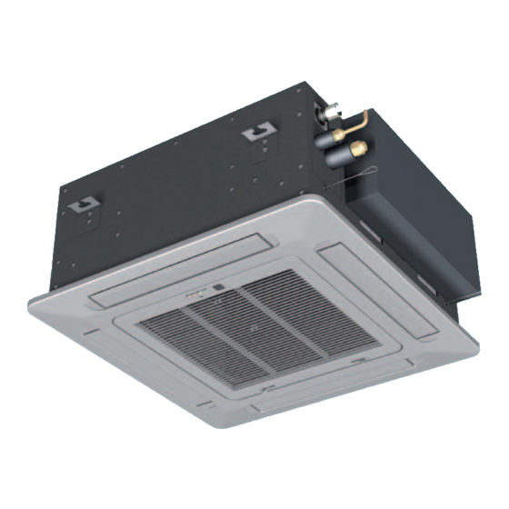
Filter Description of the RVD 521-681 DC equipment The RVD 351-1051DC room air conditioning units have a REMKO P S H RVD...AT outdoor component as RXT 1051 DC well as an indoor unit RVD...IT. The outdoor unit serves to output... -
Page 6: Operation
REMKO RVD...DC Operation The indoor unit is easy to operate using an infrared remote control. This is supplied as standard. The indoor unit beeps to acknowledge the correct transmission of data. If it is not possible to program the indoor unit using the remote control, it can also be manually operated. - Page 7 "MODE" key Key "SLEEP" Keys on the remote control Press this key to select the Pressing this key operating mode. will automatically increase or The indoor unit has 4 modes: decrease the target temperature by 1 °C every hour in cooling 1.
- Page 8 REMKO RVD...DC Remote control display Indicator arrows will be displayed according to the settings. Display on indoor unit Automatic operation Cooling mode Dehumidifying mode Fan speed Heating mode Temperature display Key functions A symbol is shown on the display to indicate that the settings are being transferred.
- Page 9 Using the key, the target temperature can be adjusted up or down by ▲/▼ Keys 1°C. The temperature range lies between 17°C and 30°C ▼ ▲ Cooling mode ▼ ▲ Automatic mode Use the MODE key to select between individual operating modes. A total MODE key of 5 modes are available: 1.
- Page 10 REMKO RVD...DC In cooling mode, the air in the room is cooled down to the adjusted Cooling MODE nominal temperature. The desired room temperature is set with the ▲/▼ keys in 1 °C increments. If the room temperature is 0.5 °C above the selected nominal temperature, then the interior unit starts to cool down the air in the room.
- Page 11 The fan speed can be adjusted with this key. A selection can be made FAN SPEED Key between low, medium, high and automatic fan speed. Automatic High Medium Speed Speed Speed Speed SWING HORIZONTAL key The oscillating function of the air fins can be adjusted with this key. This makes it possible to switch directly between a preset position and the oscillating function.
- Page 12 REMKO RVD...DC A programming function is activated using this key, which increases the SLEEP key target temperature in cooling mode by 1°C after one hour and by 2°C after 2 hours. In heating mode, the target temperature is decreased by 1 °C after one hour by 2 °C after 2 hours. The unit switches off automatically after 8 hours.
-
Page 13: Shutdown
Contact REMKO GmbH & Co. KG Type of task or your contract partner for a list of specialist companies near you. Checks/Maintenance/Inspections • •... - Page 14 REMKO RVD...DC Cleaning the cover 5. Any dirt can be cleaned off us- Guard on cover of the indoor unit ing lukewarm water and mild cleaning agents. 1. Disconnect the supply voltage To do so, turn the dirty side to the equipment.
-
Page 15: Installation Instructions For Qualified Personnel
Installation instructions for qualified personnel Important points prior to in- Select an installation location and ensures that the compres- ■ stallation which allows air to freely flow sor oil can flow back without through the inlet and outlet. obstruction. Transport the unit in its original (See section "Minimum clear- ■... - Page 16 REMKO RVD...DC Selection of the installation Wind Wall openings location A wall opening of at least 70 If the unit is being installed in ■ mm diameter and 10 mm slope Interior unit windy areas, ensure that the warm from the inside to the outside...
-
Page 17: Minimum Clearances
Air outlet ducts to compensate any pres- sure losses All values in mm (Figure 5). RVD 351DC AT RVD 521DC AT RVD 681DC AT RVD 1051DC AT 150 mm 900 mm 500 mm 150 mm 500 mm... -
Page 18: Installation
REMKO RVD...DC lection tray. Oil return measures Mounting the unit 3. Fit the ceiling cassette approx. If the outdoor component is 2 cm higher than the surface of installed at a higher level than the ceiling. (see Figure 8) the indoor unit, suitable oil return measures must be taken. -
Page 19: Installation
Connection of 5. Verify that the shape of the that they are sufficiently at- refrigerant pipes flange is correct(Figure 11). tached and take measures for the oil return, if necessary! The on-site connection of the 6. First connect and hand-tighten refrigerant pipes is made at the the refrigerant connections 10. -
Page 20: Tightness Check
REMKO RVD...DC Condensate drain Tightness check If the temperature falls below the Condensation connection - Wrong! Once all the connections have dew point, condensation will form been established, the pressure Riser pipe too far away on the cooling fins during cooling gauge station is attached as fol- mode. -
Page 21: Before Commissioning
Before Commissioning nent. See electrical connection After the tightness check has been CAUTION diagram. successfully completed, All electrical installation work connect the vacuum pump via the should be performed by spe- pressure gauge station to the valve 4. Re-assemble the unit. cialist contractors. -
Page 22: Electrical Connection Diagram
REMKO RVD...DC Electrical connection diagrams RVD 351 DC Power output Indoor unit Outdoor unit Phase cond. Phase cond. Neutral cond. Neutral cond. 230 V~, 50 Hz, Data cond. L1 / N / PE Earth conductor Earth conductor Note: Note: For the correct address selection, all 4 DIP switches (red) to ON... -
Page 23: Electrical Circuit Diagram
Electrical circuit diagram RVD 351 DC Indoor unit RVD 351 DC Outdoor unit Probe condenser Hot gas sensor Sensor environment Sensor oil yellow blue blue brown black Main board black To indoor unit blue Power management Compressor gray Reversing valve yellow Fan motor yellow... - Page 24 REMKO RVD...DC RVD 521 DC Indoor unit white purple white black blue white To CCN To outdoor unit Control Control Power output indoor unit white conductor conductor RVD 521 DC Outdoor unit Electronic Probe outlet expansion valve condenser black Hot gas sensor...
- Page 25 RVD 681 DC Indoor unit white purple white black blue white To CCN To outdoor unit Control Control Power output indoor unit conductor conductor white RVD 681 DC Outdoor unit Electronic Probe outlet expansion valve condenser black Hot gas sensor Sensor outside temperature white...
- Page 26 REMKO RVD...DC RVD 1051 DC Indoor unit white purple white black blue white To CCN To outdoor unit Control Control conductor conductor Power output indoor unit white RVD 1051 DC Outdoor unit CN16 HEAT 4-WAY FAN_H FAN_L POWER_RY TRANS IN...
-
Page 27: Add Refrigerant
Add refrigerant displays a pressure of approx. 2 The equipment contains a basic NOTE bar. quantity of refrigerant. Beyond 3. Use leak detection spray or suit- Check that the stop valves and these conditions, for refrigerant able devices to check that all valve caps are tight after carrying pipe lengths of more than 5 meters the connections are tight. - Page 28 REMKO RVD...DC Display Temperature sensor hot gas The display on the outdoor unit 12. Check all the previously Display Temperature PCB can call up the operating pa- described safety devices and 35-40 °C rameters of the plant in the above functions during the test run.
-
Page 29: Troubleshooting And Customer Service
Troubleshooting and customer service The equipment and components are manufactured using state-of-the-art production methods and tested several times to verify their correct function. If malfunctions should occur, please check the functions as detailed in the list below. Please inform your dealer if the unit is still not working correctly after all the functional checks have been performed! Malfunction Fault Possible cause... - Page 30 REMKO RVD...DC Problem display by blinker code Display outdoor Cause Required action Operation Timer Defrost Alarm unit EEPROM error Check EEPROM Communication error between PCBs Check electrical connection outdoor unit & indoor unit leads Communication error between out- door unit main board & outdoor unit...
- Page 31 Fault analysis 1. Operation light flashes at 5 Hz: fault on the 2. Defrost light flashes at 5 Hz: fault on the room temperature sensor vaporiser sensor Is the resistance of the Is the resistance of the Replace temperature Replace temperature vaporise sensor OK? temperature sensor OK? sensor...
- Page 32 REMKO RVD...DC 5. Operation and Timer lights flash at 5 Hz: EEPROM error Is the EEPROM Fit EEPROM properly fitted properly? Replace outdoor component main board 6. Operation light flashes at 5 HZ and Alarm light is on: IPM safety shutdown...
- Page 33 7. RVD 351 DC 9. Operation, Timer and Alarm lights flash at 5Hz: Operation light flashes at 5 Hz and Timer light is on: outdoor component overcurrent protection condenser temperature sensor RVD 521 DC Is the input current Alarm light flashes at 1 Hz: Fault Temperature sensor greater than 16A? condenser or outdoor unit is not working properly (look at E4, P1 and P2)
- Page 34 REMKO RVD...DC 10. Operation light flashes at 5 Hz and Defrost light is on: Hot gas temperature too high Is the temperature of Is there a Fix the leak and top up the Klixon over 115°C? refrigerant leak? Is the connection...
- Page 35 RVD 521-1051DC outdoor unit fault analysis Fault displays shown on the outdoor component Fault code Fault description Required action DISPLAY EEPROM error see page 85 / point 1 Communication error between indoor unit and outdoor component see page 85 / point 2 Communication error on outdoor component main board see page 86 / point 3 Fault on the outdoor temperature sensor...
- Page 36 REMKO RVD...DC 3. Fault code E3: communication error on main board 4. Fault code E4: fault on outside temperature of the outdoor component sensor T4 or condenser sensor T3 Does LED1 flash on the Is the condenser Replace Connect condenser...
- Page 37 6. Fault code P1: high pressure fault Is the connecting cable Correct from the high pressure connection switch to the main board OK? High pressure switch may be defective Bypass the high Replace the high pressure switch on the pressure switch circuit board.
- Page 38 REMKO RVD...DC 7. Fault code P2: low pressure fault Is the connecting cable Correct from the lower pressure connection switch to the main board OK? Low pressure switch may be defective Bypass the low pressure Replace the high switch on the circuit pressure switch board.
- Page 39 8. Fault code P3: compressor overcurrent protection has tripped Is the input current greater than 20A? Check refrigerant pipes Is the outdoor Switch off unit temperature too high? Is the function of the Ensure fan functions fan on the outdoor properly component OK? Is the register of the...
- Page 40 REMKO RVD...DC 9. Fault code P4: hot gas temperature too high Fix the leak and top up Is there a Is the hot gas refrigerant leak? temperature over 115°C? Is the connection Establish a proper between the sensor connection and circuit board OK?
- Page 41 11. Fault code P6: IPM power board safety shutdown Ensure the correct Is the input voltage Is the voltage range supply voltage between P and N of between P and N of the IPM module 230V the IPM module OK? / the frequency 50 Hz? Are all the electrical Connect cables...
-
Page 42: Resistances Of The Temperature- And Hot Gas Sensors
REMKO RVD...DC Resistances of the temperature sensors (Table 1) Temp. Resistance kΩ Temp. Resistance kΩ (°C) Rmax R(t) Normal Rmin (°C) Rmax R(t) Normal Rmin 116.539 106.732 96.920 11.883 11.496 11.112 110.231 100.552 91.451 11.327 10.971 10.617 103.743 94.769 86.328 10.800... - Page 43 Temp. Resistance kΩ (°C) Rmax R(t) Normal Rmin 2.154 2.026 1.903 2.077 1.953 1.833 2.004 1.883 1.766 1.934 1.816 1.702 1.867 1.752 1.641 1.802 1.690 1.582 1.740 1.631 1.525 1.680 1.574 1.471 1.622 1.519 1.419 1.567 1.466 1.369 1.514 1.416 1.321 1.463 1.367...
- Page 44 REMKO RVD...DC Resistances of the hot gas sensors (Table 2) °C kΩ °C kΩ °C kΩ °C kΩ 542.7 62.73 11.79 3.113 511.9 59.98 11.38 3.025 57.37 10.99 2.941 455.9 54.89 10.61 2.86 430.5 52.53 10.25 2.781 406.7 50.28 9.902 2.704...
-
Page 45: Unit Dimensions
Unit dimensions RVD 351-521 DC Indoor unit RVD 681-1051 DC Indoor unit RVD 351-1051 DC Outdoor unit RVD 351 DC RVD 521 DC RVD 681 DC RVD 1051 DC All values in mm We reserve the right to modify the dimensions and constructional design as part of the ongoing technical development process. -
Page 46: Exploded View
REMKO RVD...DC Exploded view RVD 351DC IT to RVD 1051DC IT We reserve the right to modify the dimensions and constructional design as part of the ongoing technical development process. Spare parts list Designation RVD 351 DC IT RVD 521 DC IT RVD 681 DC IT RVD 1051 DC IT... -
Page 47: Exploded View
Exploded view RVD 351-1051 DC AT We reserve the right to modify the dimensions and constructional design as part of the ongoing technical development process. Spare parts list Designation RVD 351 DC AT RVD 521 DC AT RVD 681 DC AT RVD 1051 DC AT 1110990 1110991... -
Page 48: Technical Data And Performance Charts For Heating
650 / 650 950 / 950 18,0 21,0 29,0 30,0 Weight RVD 351DC AT RVD 521DC AT RVD 681DC AT RVD 1051DC AT Corresponding outdoor unit Operating range - cooling °C +5 - +43 Operating range - heating °C -5 - +24 Air flow rate, max. - Page 49 Performance charts for heating RVD 521 DC RVD 351 DC 7.00 6.50 6.00 5.50 5,00 4.50 4.00 3.50 3.00 1,40 1.70 1,20 1.60 1,00 1.50 0,80 1.40 0,70 1.30 0,50 1.20 0,30 1.10 -15 -12 -15 -11 -9 Outdoor temperature Outdoor temperature Außentemperatur RVD 1051 DC...
-
Page 50: Ec-Declaration Of Conformity
D - 32791 Lage Equipment (machinery) - Implementation: Inverter ceiling-mounted air conditioner in split design Series / Model: REMKO RVD 351DC, RVD 521 DC, RVD 681 DC, RVD 1051 DC Series / Class Number: 548..., 549..., 713..., 714... Applicable regulations: MA DIR. - Page 52 REMKO provides not only a well-developed distribution network in Germany and abroad, but also unusually highly skilled professionals in distribution. REMKO staff in the field are more than mere salespeople: they must primarily act as advisers in air conditioning and heating technology for our customers.
Need help?
Do you have a question about the RVD 351DC and is the answer not in the manual?
Questions and answers