
Subscribe to Our Youtube Channel
Related Manuals for Check Point 12000


Summary of Contents for Check Point 12000
- Page 1 Check Point 12000 Appliances Getting Started Guide 20 July 2011 Models: P-210, P-220, and P-230 CP_12000_Appliances_GettingStart1 1 CP_12000_Appliances_GettingStart1 1 20 July 2011 4:04:33 PM 20 July 2011 4:04:33 PM...
- Page 2 Check Point. While every precaution has been taken in the preparation of this book, Check Point assumes no responsibility for errors or omissions. This publication and features described herein are subject to change without notice.
-
Page 3: Safety, Environmental, And Electronic Emissions Notices
Welcome Safety, Environmental, and Electronic Emissions Notices Read the following warnings before setting up or using the appliance. Warning - Do not block air vents. A minimum 1/2-inch clearance is required. Warning - This appliance does not contain any user-serviceable parts. Do not remove any covers or attempt to gain access to the inside of the product. - Page 4 Welcome Disconnect the system board power supply from its power source before you connect or disconnect cables or install or remove any system board components. Failure to do this can result in personnel injury or equipment damage. Avoid short-circuiting the lithium battery; this can cause it to superheat and cause burns if touched.
- Page 5 Welcome Handling the cord on this product will expose you to lead, a chemical known to the State of California to cause cancer, and birth defects or other reproductive harm. Wash hands after handling. Federal Communications Commission (FCC) Statement: For a Class A digital device or peripheral Note: This equipment has been tested and found to comply with the limits for a Class A digital device, pursuant to Part 15 of the FCC Rules.
- Page 6 Welcome Canadian Department Compliance Statement: This Class A digital apparatus complies with Canadian ICES-003. Cet appareil numérique de la classe A est conforme à la norme NMB-003 du Canada. This Class B digital apparatus complies with Canadian ICES-003. Cet appareil numérique de la classe B est conforme à...
- Page 7 Welcome This product is in conformity with Low Voltage Directive 2006/95/EC, and complies with the requirements in the Council Directive 2006/95/EC relating to electrical equipment designed for use within certain voltage limits and the Amendment Directive 93/68/EEC. Product Disposal This symbol on the product or on its packaging indicates that this product must not be disposed of with your other household waste.
- Page 8 CP_12000_Appliances_GettingStart8 8 CP_12000_Appliances_GettingStart8 8 20 July 2011 4:04:33 PM 20 July 2011 4:04:33 PM...
-
Page 9: Table Of Contents
Attaching the Rail Plates ................17 Attaching the Appliance Rails to the Appliance ..........18 Installing the Appliance in the Rack ...............20 Rack Mounting Check Point 12400 and 12600 ...........21 Attaching the Ear Mount Brackets to the Appliance ........21 Attaching the Rail Plates ................22 Attaching the Appliance Rails to the Appliance ..........23... - Page 10 Removing a Hard Disk Drive ................47 Installing a Hard Disk Drive ................47 Replacing Hard Disk Drives on Check Point 12400 and 12600 ......47 Removing a Hard Disk Drive ................48 Installing a Hard Disk Drive ................48 Restoring Factory Defaults ..................
-
Page 11: Introduction
Terminology Welcome Thank you for choosing Check Point 12000 Appliances. We hope that you will be satisfied with this system and our support services. Check Point products provide your business with the most up to date and secure solutions available today. -
Page 12: Shipping Carton Contents
This document provides: A brief overview of essential Check Point 12000 Appliances concepts and features A step by step guide to getting Check Point 12000 Appliances up and running Note - Screenshots in this guide may apply only to the highest model to which this guide applies. -
Page 13: Terminology
Terminology Terminology The following terms are used in this guide: Gateway security enforcement point. Security Policy: The policy created by the system administrator that regulates the flow of incoming and outgoing communication. Security Management Server: The server used by the system administrator to manage on the Security Management Server and downloaded to the gateway. - Page 14 CP_12000_Appliances_GettingStart14 14 CP_12000_Appliances_GettingStart14 14 20 July 2011 4:04:33 PM 20 July 2011 4:04:33 PM...
-
Page 15: Rack Mounting
In This Chapter Rack Mounting Hardware and Tools Rack Mounting Check Point 12200 Rack Mounting Check Point 12400 and 12600 Rack Mounting Hardware and Tools You must install rack mounting hardware on the appliance before you can mount it in a rack. -
Page 16: Rack Mounting Check Point 12200
Rack Mounting Check Point 12200 Rack Mounting Tools Philips screwdriver. A magnetic head is recommended to hold screws in place and retrieve dropped screws. A powered screwdriver is also useful. Rack Mounting Check Point 12200 Attaching the Ear Mount Brackets to the Appliance Attach the two ear mount brackets to the front of the appliance. -
Page 17: Attaching The Rail Plates
Rack Mounting Check Point 12200 Attaching the Rail Plates Attach the rail plates to the appliance rails to connect the appliance to the rear vertical rails of the rack. Item Description Appliance rail Rail plate Note - The appliance rail screws have 8 mm heads. -
Page 18: Attaching The Appliance Rails To The Appliance
Rack Mounting Check Point 12200 This figure shows the assembled rail plate and appliance rail. Attaching the Appliance Rails to the Appliance Attach the appliance rails to the sides of the appliance. Position the rail plates to connect the appliance rails to the rear of the rack. - Page 19 Rack Mounting Check Point 12200 To attach the appliance rails: 1. Set the appliance rail on the side of the appliance. The ridges on the appliance rails point to the appliance. This diagram shows the appliance rail and rail plate positioned correctly: 2.
-
Page 20: Installing The Appliance In The Rack
Rack Mounting Check Point 12200 Installing the Appliance in the Rack Install the appliance in the rack. It may be necessary to adjust the appliance rails to secure the appliance to the rack. Important - Two people are required to install the appliance in a rack in order to prevent personal injury or damage to the appliance. -
Page 21: Rack Mounting Check Point 12400 And 12600
Rack Mounting Check Point 12400 and 12600 Rack Mounting Check Point 12400 and 12600 Attaching the Ear Mount Brackets to the Appliance Attach the two ear mount brackets to the front of the appliance. To attach the ear mount brackets to the appliance: 1. -
Page 22: Attaching The Rail Plates
Rack Mounting Check Point 12400 and 12600 Attaching the Rail Plates Attach the rail plates to the appliance rails to attach the appliance to the rear vertical rails of the rack. Item Description Appliance rail Rail plates To attach the rail plates: 1. -
Page 23: Attaching The Appliance Rails To The Appliance
Rack Mounting Check Point 12400 and 12600 This figure shows the assembled rail plate and appliance rail. Attaching the Appliance Rails to the Appliance Attach the appliance rails to the sides of the appliance. The rail plates are positioned to connect the appliance rails to the rear of the rack. -
Page 24: Installing The Appliance In The Rack
Rack Mounting Check Point 12400 and 12600 To attach the appliance rails: 1. Set the appliance rail on the side of the appliance. The ridges on the appliance rails point to the appliance. This diagram shows the appliance rail and rail plate positioned correctly: 2. -
Page 25: Configuring Check Point 12000 Appliances
The workflow for configuring Check Point 12000 Appliances is: 1. Connect the cables and power on the appliance. 2. Use the First Time Configuration Wizard to configure the appliance. 3. Add the Check Point 12000 Appliances object in SmartDashboard and install a policy. In This Chapter Powering On... -
Page 26: Using The First Time Configuration Wizard
The appliance is ready for use when the model number is displayed. Using the First Time Configuration Wizard Perform the initial configuration of Check Point 12000 Appliances using the First Time Configuration Wizard. You can use the following commands at any time: Click Quit to exit. -
Page 27: Starting The First Time Configuration Wizard
The Welcome page summarizes the steps of the First Time Configuration Wizard. Appliance Date and Time Setup Configure date and time in the Date and Time Setup page. Click Apply. Configuring Check Point 12000 Appliances Page 27 CP_12000_Appliances_GettingStart27 27 CP_12000_Appliances_GettingStart27 27... -
Page 28: Network Connections
Using the First Time Configuration Wizard Network Connections Configure the network connections in the Network Connections page. You can modify the Management IP address and connectivity is preserved. A secondary interface is created automatically to preserve connectivity. This interface can be removed after the wizard is completed in the Network >... - Page 29 This section describes how to configure the appliance for locally managed deployment. Check Point 12000 Appliances Cluster Configure the cluster type. If you select This appliance is part of a Check Point 12000 Appliances Cluster, the options are: Primary cluster member...
-
Page 30: Summary
Using the First Time Configuration Wizard Centrally Managed Deployment This section describes how to configure the appliance for centrally managed deployment. Gateway Type Configure the gateway type for a Centrally Managed appliance. Choose one of: Standard Gateway This Gateway is a member of a cluster This Gateway uses a dynamically assigned IP Web/SSH and GUI Clients Configuration Define the clients that are allowed to connect to the appliance using a web browser or SSH... -
Page 31: Creating The Network Object
Creating the Network Object Creating the Network Object Configure the Check Point 12000 Appliances as a gateway object in the Security Management Server database. To create the network object in SmartDashboard: 1. Launch SmartDashboard. 2. Configure a new gateway object for the appliance. - Page 32 CP_12000_Appliances_GettingStart32 32 CP_12000_Appliances_GettingStart32 32 20 July 2011 4:04:33 PM 20 July 2011 4:04:33 PM...
-
Page 33: Check Point 12000 Appliances Hardware
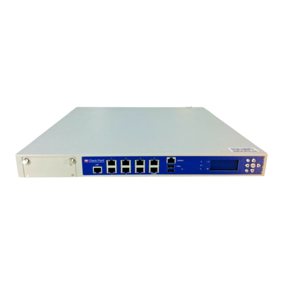
Chapter 4 Check Point 12000 Appliances Hardware This chapter provides instructions for installing and removing hardware components on Check Point 12000 Appliances. In This Chapter Front Panel Components Rear Panel Components Using the LCD Panel Front Panel Components The section describes the hardware on the front panel of the appliance. - Page 34 Front Panel Components Item Component Description Built in Ethernet ports LAN1 - LAN7 Management Ethernet connection to a remote management workstation configuration port USB ports Console port A serial connection to the appliance using a terminal emulation program such as HyperTerminal or PuTTY System LEDs System power, system status, and hard disk activity LCD display screen...
-
Page 35: Check Point 12400 Front Panel
Expansion line card 8 Port 10/100/1000Base-T RJ-45. Model: CPAP-ACC-8-1C USB ports Synchronization For synchronizing with cluster members or a high availability peer port Check Point 12000 Appliances Hardware Page 35 CP_12000_Appliances_GettingStart35 35 CP_12000_Appliances_GettingStart35 35 20 July 2011 4:04:33 PM 20 July 2011 4:04:33 PM... - Page 36 Front Panel Components Item Component Description Expansion line card Expansion slot Expansion line card Expansion slot Expansion Line Card Options Expansion line cards can have two, four, or eight ports. These types of expansion line cards are available: Model Description CPAP-ACC-2-10F 2 Port 10GBase-F SFP+ (without transceivers) CPAP-ACC-4-1C...
-
Page 37: Check Point 12600 Front Panel
Expansion line card 8 Port 10/100/1000Base-T RJ-45. Model: CPAP-ACC-8-1C USB ports Synchronization For synchronizing with cluster members or a high availability peer port Check Point 12000 Appliances Hardware Page 37 CP_12000_Appliances_GettingStart37 37 CP_12000_Appliances_GettingStart37 37 20 July 2011 4:04:33 PM 20 July 2011 4:04:33 PM... - Page 38 Front Panel Components Item Component Description Expansion line card 4 Port 10/100/1000Base-T RJ-45. Model: CPAP-ACC-4-1C Expansion line card Expansion slot Expansion Line Card Options Expansion line cards can have two, four, or eight ports. These types of expansion line cards are available: Model Description...
-
Page 39: Rear Panel Components
Hard disk drives When monitoring the disks using the raid_diagnostic command, DiskID 0 is the top disk, and DiskID 1 is the bottom disk. Check Point 12000 Appliances Hardware Page 39 CP_12000_Appliances_GettingStart39 39 CP_12000_Appliances_GettingStart39 39 20 July 2011 4:04:33 PM... -
Page 40: Check Point 12400 And 12600 Rear Panel
Using the LCD Panel Check Point 12400 and 12600 Rear Panel Item Component Description Main power switch Power supply units If a power supply fails or is not connected to the outlet, an alarm sounds continuously Using the LCD Panel The appliance has an LCD panel that can be used to perform basic management operations. - Page 41 Cancel the IP change when the cursor is located on the first digit Change current digit Check Point 12000 Appliances Hardware Page 41 CP_12000_Appliances_GettingStart41 41 CP_12000_Appliances_GettingStart41 41 20 July 2011 4:04:33 PM...
-
Page 42: Customer Replaceable Parts
Replacing Power Supplies Check Point 12000 Appliances have a redundant power supply. This section explains how to remove and install a power supply or placeholder unit. Note - If both power supply slots are not populated, a continuous alarm sounds. - Page 43 Replacing Power Supplies Item Description Power switch Power cord socket Release lever Extraction handle Power supply unit Customer Replaceable Parts Page 43 CP_12000_Appliances_GettingStart43 43 CP_12000_Appliances_GettingStart43 43 20 July 2011 4:04:33 PM 20 July 2011 4:04:33 PM...
-
Page 44: Removing Power Supplies
Replacing Power Supplies Removing Power Supplies This section describes how to remove a power supply or placeholder unit from the appliance. To remove a power supply unit: 1. If the alarm sounds, press the red alarm button to the right of the power supply. The alarm stops. -
Page 45: Replacing Expansion Line Cards
Important - Make certain that you are electromagnetically grounded when performing the following procedures. Static electricity can damage the appliance. Check Point 12200 Appliance The built-in Ethernet ports (LAN1 - LAN8) are not customer replaceable. Check Point 12400 and 12600 Appliances Customer Replaceable Parts Page 45 CP_12000_Appliances_GettingStart45 45... -
Page 46: Removing Expansion Line Cards
6. Tighten the retaining screws on the expansion line card. Replacing Hard Disk Drives on Check Point 12200 This section describes how to remove or install a hard disk drive in a Check Point 12200 appliance. Page 46 CP_12000_Appliances_GettingStart46 46... -
Page 47: Removing A Hard Disk Drive
3. Using the key supplied in the toolkit, lock the new drive. Replacing Hard Disk Drives on Check Point 12400 and 12600 This section describes how to remove or install a hard disk drive in a Check Point 12400 or 12600 appliance. Customer Replaceable Parts... -
Page 48: Removing A Hard Disk Drive
Replacing Hard Disk Drives on Check Point 12400 and 12600 Removing a Hard Disk Drive To remove a hard disk drive from a Check Point 12400 or 12600: 1. Using the key supplied in the toolkit, unlock the drive. 2. Slide the release latch toward the left. The extraction handle pops out. -
Page 49: Restoring Factory Defaults
Chapter 5 Restoring Factory Defaults As part of the troubleshooting process, it may be necessary to restore the appliance to its factory default settings. You can restore your appliance to the factory default image using one of the following methods: Using the WebUI Through the console boot menu Using the LCD panel... -
Page 50: Restoring Using The Console Boot Menu
Restoring Using the Console Boot Menu Restoring Using the Console Boot Menu To restore the appliance to its default factory configuration using the console boot menu: 1. Connect the supplied DB9 serial cable to the console port on the front of the appliance. 2. -
Page 51: Restoring Using The Lcd Panel
Restoring Using the LCD Panel Restoring Using the LCD Panel To restore the appliance to its default factory configuration using the LCD Panel keys: 1. Reboot or power on the appliance. 2. When the countdown begins, press any of the arrow keys. The Boot menu appears. - Page 52 CP_12000_Appliances_GettingStart52 52 CP_12000_Appliances_GettingStart52 52 20 July 2011 4:04:33 PM 20 July 2011 4:04:33 PM...
-
Page 53: Registration And Support
Check Point software. Check Point documentation is available on the Check Point Support Center (http://supportcenter.checkpoint.com). Be sure to also use the Online Help when you are working with the Check Point SmartConsole clients. Page 53 CP_12000_Appliances_GettingStart53 53... - Page 54 CP_12000_Appliances_GettingStart54 54 CP_12000_Appliances_GettingStart54 54 20 July 2011 4:04:34 PM 20 July 2011 4:04:34 PM...
-
Page 55: Compliance Information
This appendix contains declaration of conformity, compliance, and related regulatory information. In This Appendix Declaration of Conformity Declaration of Conformity Check Point Software Technologies Ltd. 5 Ha'Solelim Street, Tel Aviv 67897, Israel Declare that under our sole responsibility the products Model Number: P-210, P-220, and P-230... - Page 56 Declaration of Conformity ICES-003, Class A Information Technology Equipment - Radio Disturbance Characteristics CISPR22 Information Technology Equipment - Radio Disturbance Characteristics EN55022, Class A Information Technology Equipment - Radio Disturbance Characteristics EN 61000-3-2 Information Technology Equipment - Harmonics Characteristics EN61000-3-3 Information Technology Equipment - Flicker Characteristics EN 55024...
- Page 57 Declaration of Conformity The product herewith complies with the requirements of the EU Directive 2006/95/EC and the EMC Directive 2004/108/EC Date and Place of issue: July, 2011, Tel Aviv, Israel FCC Notice (US) This equipment has been tested and found to comply with the limits for a Class A digital device, pursuant to part 15 of the FCC Rules.
Need help?
Do you have a question about the 12000 and is the answer not in the manual?
Questions and answers