
Related Manuals for Vision VN7X


Summary of Contents for Vision VN7X
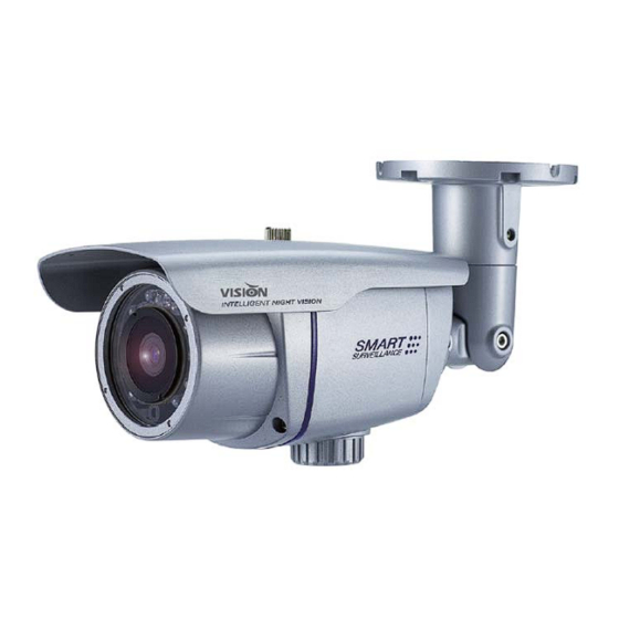
- Page 1 HARDWARE INSTALLATION GUIDE VN7X Outdoor IR Bullet IP Camera Model : VN7XSM3Ti / VN7XSM3i / VN7XSMi / VN7XEHi Version 1. 0. 0 Released on 2 of July., 2012 Vision Hitech Co., Ltd. Page 1 / 9...
- Page 2 PRECAUTIONS By selecting this product, you have decided to use a professional device that guarantees highest quality and reliability. We would like to thank you very much for your confidence and kindly ask you to read the following instructions carefully before installation and operation in order to take full advantage of all quality features regarding this product. The lighting flash with an arrowhead symbol, within an equilateral triangle is intended to alert the user to the presence of non‐insulated dangerous voltage within the product’s enclosure that may be of sufficient magnitude to constitute a risk of electric shock to persons. ...
-
Page 3: Table Of Contents
Table of content Hardware Installation Guide Precautions ‐‐‐‐‐‐‐‐‐‐‐‐‐‐‐‐‐‐‐‐‐‐‐‐‐‐‐‐‐‐‐‐‐‐‐‐‐‐‐‐‐‐‐‐‐‐‐‐‐‐‐‐‐‐‐‐‐‐‐‐‐‐‐‐‐‐‐‐‐‐‐‐‐‐‐‐‐‐‐‐‐‐‐‐‐‐‐‐‐‐‐‐‐‐‐‐‐‐‐‐ 4 1. 2. Limitation of liability ‐‐‐‐‐‐‐‐‐‐‐‐‐‐‐‐‐‐‐‐‐‐‐‐‐‐‐‐‐‐‐‐‐‐‐‐‐‐‐‐‐‐‐‐‐‐‐‐‐‐‐‐‐‐‐‐‐‐‐‐‐‐‐‐‐‐‐‐‐‐‐‐‐‐‐‐‐‐‐‐‐‐‐‐‐‐‐‐ 4 3. Disclaimer of warranty ‐‐‐‐‐‐‐‐‐‐‐‐‐‐‐‐‐‐‐‐‐‐‐‐‐‐‐‐‐‐‐‐‐‐‐‐‐‐‐‐‐‐‐‐‐‐‐‐‐‐‐‐‐‐‐‐‐‐‐‐‐‐‐‐‐‐‐‐‐‐‐‐‐‐‐‐‐‐‐‐‐‐‐‐‐ 4 4. Package Contents ‐‐‐‐‐‐‐‐‐‐‐‐‐‐‐‐‐‐‐‐‐‐‐‐‐‐‐‐‐‐‐‐‐‐‐‐‐‐‐‐‐‐‐‐‐‐‐‐‐‐‐‐‐‐‐‐‐‐‐‐‐‐‐‐‐‐‐‐‐‐‐‐‐‐‐‐‐‐‐‐‐‐‐‐‐‐‐‐‐‐‐‐‐ 5 5. Cable Connection ‐‐‐‐‐‐‐‐‐‐‐‐‐‐‐‐‐‐‐‐‐‐‐‐‐‐‐‐‐‐‐‐‐‐‐‐‐‐‐‐‐‐‐‐‐‐‐‐‐‐‐‐‐‐‐‐‐‐‐‐‐‐‐‐‐‐‐‐‐‐‐‐‐‐‐‐‐‐‐‐‐‐‐‐‐‐‐‐‐‐‐‐‐ 6 6. Installation ‐‐‐‐‐‐‐‐‐‐‐‐‐‐‐‐‐‐‐‐‐‐‐‐‐‐‐‐‐‐‐‐‐‐‐‐‐‐‐‐‐‐‐‐‐‐‐‐‐‐‐‐‐‐‐‐‐‐‐‐‐‐‐‐‐‐‐‐‐‐‐‐‐‐‐‐‐‐‐‐‐‐‐‐‐‐‐‐‐‐‐‐ 7~9 7. Dimension (mm) ‐‐‐‐‐‐‐‐‐‐‐‐‐‐‐‐‐‐‐‐‐‐‐‐‐‐‐‐‐‐‐‐‐‐‐‐‐‐‐‐‐‐‐‐‐‐‐‐‐‐‐‐‐‐‐‐‐‐‐‐‐‐‐‐‐‐‐‐‐‐‐‐‐‐‐‐‐‐‐‐‐‐‐‐‐‐‐‐‐‐‐‐‐‐‐ 10 ... -
Page 4: Precautions
1. Precautions Please read the manual carefully before the installation in order to set up the camera correctly and to obtain the best picture quality. Please keep the manual in good condition for your future reference and service application. Installation and services should be only carried out by an authorized personnel according to local safety regulations. If any liquid or solid matter gets into the housing, immediately disconnect the camera from power supply and have it checked by your authorized dealer before reusing. Avoid installing the camera at extremely hot or cold places. If you are not a certified person, never try to dismantle the camera. To avoid electric shock, never remove the screws or covers. There are no parts inside that need maintenance by the user. All maintenance should be carried out by qualified personnel. Avoid installing the camera at a place of high humidity. Avoid installing the camera at the place exposed to gas or oil. Keep the top glass of the lens always clean in order to obtain the best picture quality all the time. Be careful not to be stained by fingerprint. Don't face the camera directly toward sunlight or sunlight reflecting area. CCD may go defective at this condition. Please give a special attention to keep the unit from dangerous drop or external shock during the process of transportation or handling. Never try to touch the camera in wet hand. It may cause an electric shock. Do not expose the camera to radioactivity. It causes a serious damage on the CCD. 2. Limitation of liability This publication is provided “AS IS” without warranty of any kind, either express or implied, including but not limited to, the implied warranties of merchantability, fitness for any particular purpose, or non‐infringement of the ... -
Page 5: Package Contents
(2) Personal injury or any damage caused by inappropriate use or negligent operation of the user; (3) Unauthorized disassemble, repair or modification of the product by the user; (4) Inconvenience or any loss arising when images are not displayed, due to any reason or cause including any failure or problem of the product; (5) Any problem, consequential inconvenience, or loss or damage, arising out of the system combined by the devices of third party. (6) Any claim or action for damages, brought by any person or organization being photogenic subject, due to violation of privacy with the result of that surveillance‐camera's picture, including saved data, for some reason, becomes public or is used for the purpose other than surveillance. 4. Package Contents Crossover LAN Hardware Installation IP Camera x 1 Cable x 1 ... -
Page 6: Cable Connection
5. Cable Connection Power Connector (DC12V) Network Connector Analog Video Out(YELLOW) Sensor In/Alarm Out Audio-in (RED) Audio-out (WHITE) This IP camera uses 12VDC for power source. Please make sure to use a UL/CE approved and 12VDC regulated power supply for input power. Alarm In/out Cable ● COLOR DESCRIPTION Sky Blue/Black Sky Blue ALARM INPUT 1 Violet ALARM OUT... -
Page 7: Installation
6. Installation How to mount to ceiling / wall ■ ① Drill three screw holes on the wall plate to fix three plastic anchors (supplied) in the holes. ② Fix the plastic anchors in the holes. ③ Position the mounting bracket on the screw points. ④... - Page 8 Axis Adjustment ■ ① Pan 360˚ Slightly loosen Pan bolt, then adjust pan of the camera using a serration on the bracket and tighten the bolt firmly again ② Tilt 180˚ Slightly loosen Tilt bolt, then adjust tilt of the camera using a serration on the bracket and tighten the bolt firmly again ③...
-
Page 9: Dimension (Mm)
7. Dimension (mm) Page 9 / 9...
Need help?
Do you have a question about the VN7X and is the answer not in the manual?
Questions and answers