
Related Manuals for EM Acoustics i-C12


Summary of Contents for EM Acoustics i-C12
- Page 1 Product User Manual v1 November 2019 L O U D S P E A K E R S D E F I N E D...
-
Page 2: Table Of Contents
Page 2 of 27 Contents DECLARATION OF CONFORMITY ........................ 4 1.0 - Introduction ............................. 5 Unpacking............................... 5 2.0 – i-C12 & Accessories ..........................6 i-C12 ................................. 6 IB-hC12 ................................6 IB-vC12................................6 3.0 – Simulation ..............................7 Ease Focus 3 ..............................7 4.0 - Safety Considerations.......................... - Page 3 6.4.2 – Crossover Cable Use ......................19 7.0 – Servicing Information ........................20 7.1 – i-C12: Removing the grille ......................20 7.2 – i-C12: Removing the coaxial drive unit ................. 21 Appendix A – Technical Specifications ....................22 i-C12 coaxial passive installation loudspeaker ................22 Appendix B –...
-
Page 4: Declaration Of Conformity
The packaging supplied with this product is recyclable. Please retain all packaging, however if disposing of this packaging please ensure that you comply with local recycling regulations. These products also all comply to the RoHS Directive 2002/95/EC. i-C12 User Manual v1 November 2019... -
Page 5: Introduction
Page 5 of 27 1.0 - Introduction Thank you for purchasing the highly acclaimed i-C12 from EM Acoustics. This product has been designed and rigorously tested to give you the utmost in sonic performance and many years of reliable, trouble-free operation. Please take the time to read this user manual thoroughly to ensure you get the best performance from your system and to ensure you set it up correctly and safely. -
Page 6: I-C12 & Accessories
NET/SHIPPING WEIGHT: IB-hC12 Horizontal mounting yoke The IB-hC12 is a simple and effective means of mounting the i-C12 horizontally in both temporary and permanent applications. It is secured to the cabinet by means of M10 threaded locking knobs into the top and bottom of the loudspeaker to mount it in a landscape format. -
Page 7: Simulation
Tutorials for Ease Focus 3 are available from with the application itself. For training on the design and implementation of i-C12 loudspeakers including the specific use of Ease Focus 3, please contact your local distributor. -
Page 8: Safety Considerations
General Considerations in use Loudspeaker systems are potentially dangerous objects if used incorrectly. Please ensure that you read this section fully, and contact EM Acoustics or your local dealer should you be in any doubt over correct operation procedures. Personal Injury Never stand in the immediate vicinity of loudspeakers when in use at high level. -
Page 9: Ground Stacking
EM Acoustics is in no way liable for any loss, damage or injury caused by such practice. Do not modify or alter the i-C12 loudspeaker or accessories, nor use them in any way other than that described in this manual. Rigging components supplied with the i-C12 are in no way interchangeable and should not be used as such. -
Page 10: Secondary Safeties
In most cases, annual independent tests & inspections carried out by a suitably approved and qualified inspector will be required. EM Acoustics recommends detailed logbooks be kept of all inspections and load tests to ensure an accurate record is kept of the testing for each EM Acoustics rigging accessory. -
Page 11: Rigging & Mounting Options
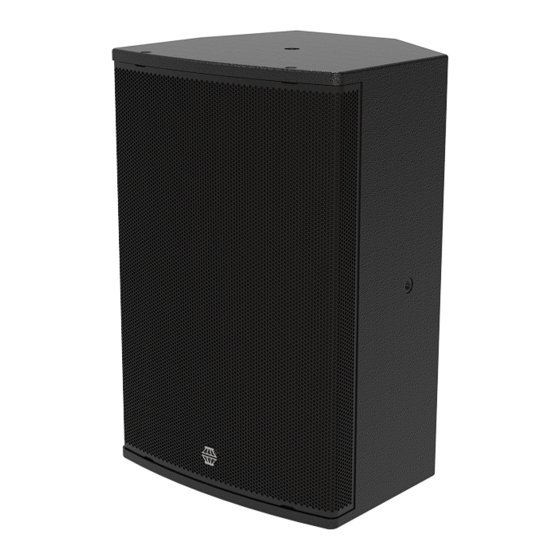
Page 11 of 27 5.0 – Rigging & Mounting Options 5.1 – i-C12 Cabinet Overview Top/Bottom M10 mounting point Side M10 mounting point Omnimount/Powerdrive attachment point i-C12 User Manual v1 November 2019... -
Page 12: Using The Ib-Vc12
Page 12 of 27 5.2 – Using the IB-vC12 The IB-vC12 is intended to mount the i-C12 vertically – either using a hook clamp or similar from above, or a pole mount adapter to mount on a stand yet allowing enclosure tilt. The procedure for attaching the IB-vC12 to the loudspeaker is the same regardless of the mounting orientation. -
Page 13: Safety Point
(M8 on the rear, M10 on the top/bottom and sides). Safeties should always be arranged so that the loudspeaker cannot drop in the event of a primary attachment point failing. i-C12 User Manual v1 November 2019... -
Page 14: Using Powerdrive Or Omnimount Fittings
Using a 5mm Allen key, remove the four M8 countersunk socket head bolts on the rear of the i-C12. The mounting bracket can then be attached using the bolts supplied with the bracket – they must be M8 thread, minimum 30mm in length. Ensure flat washers are in contact with the bracket, and the spring washer is in between the bolt head and the flat washer. -
Page 15: Powering The System
Page 15 of 27 6.0 – Powering the System The i-C12 can be powered from any amplifier & DSP combinations with the relevant high & low pass filter, and limiter settings. However, due to the self-contained nature of the package, the use of DQ Series advanced system amplifiers is highly recommended. The... -
Page 16: Amplifier Requirements
All of the DQ Series advanced system amplifiers can be used to power the i-C12. The following table shows the maximum number of i-C12 that can be connected per... -
Page 17: Presets And Settings
The i-C12 is designed with a significant amount of system headroom, so applying EQ is perfectly acceptable within sensible limits. -
Page 18: Use With The Dq Series Advanced System Amplifiers
Page 18 of 27 6.3 - Use with the DQ Series Advanced System Amplifiers The i-C12 will perform best when using DQ Series advanced system amplifiers, as not only are they state-of-the-art amplifiers, but the onboard DSP provides appropriate high/low pass filter settings and limiters to get the best from your loudspeakers. -
Page 19: System Connectivity
Because pins 2+/2- are linked through inside all EM Acoustics loudspeakers, using a 4-core cable to one loudspeaker (carrying two different signals) allows a crossover cable to be used to link out of the first loudspeaker into another, thereby feeding it from a separate signal. -
Page 20: Servicing Information
To replace the grille, position the grille on the front of the i-C12 and ensure the threaded fittings on the grille are lined up with the mounting holes – gentle pressure may be required. Replace all of the M6x30 countersunk socket screws and ensure they are all are started in their threads before beginning to tighten. -
Page 21: I-C12: Removing The Coaxial Drive Unit
Page 21 of 27 7.2 – i-C12: Removing the coaxial drive unit TOOLS REQUIRED: 5mm Allen key Complete step 7.1 above to remove the grille. Using a 5mm Allen key, remove the eight M6x30 socket cap screws that secure the drive unit. Ensure that you collect the spring washers as well as the machine screws from each mounting bolt location. -
Page 22: Appendix A - Technical Specifications
Page 22 of 27 Appendix A – Technical Specifications i-C12 coaxial passive installation loudspeaker Dimensions (HxWxD): 560 x 370 x 350mm (14.6” x 14.6” x 13.8”) Net/Shipping Weight: 22.6kg/24.7kg (49.7/54.3lbs) Frequency Response (+/- 3dB) 65Hz – 20kHz Dispersion 80° conical Drive Units: 12”... -
Page 23: Appendix B - Technical Drawings
Page 23 of 27 Appendix B – Technical Drawings i-C12 User Manual v1 November 2019... - Page 24 Page 24 of 27 i-C12 User Manual v1 November 2019...
- Page 25 Page 25 of 27 i-C12 User Manual v1 November 2019...
-
Page 26: Appendix C - Spare Parts List
Page 26 of 27 Appendix C – Spare Parts List Order Code Description 01A503 CAD-1202 replacement 12” / 1.3” coaxial drive unit 04A039 RFG-i-C12 replacement grille/fabric for i-C12 07A038 PX-i-C12 replacement passive crossover assembly for i-C12 i-C12 User Manual v1 November 2019... -
Page 27: Appendix D - Warranty Information
Serial numbers must be quoted in all correspondence relating to the claim. EM Acoustics or its representatives are in no way liable for any loss or damage in transit, and hence it is recommended that the sender insure the shipment. EM Acoustics will pay for return freight should the repair be covered under warranty.
Need help?
Do you have a question about the i-C12 and is the answer not in the manual?
Questions and answers