
Related Manuals for Supermicro Altus 1804i


Summary of Contents for Supermicro Altus 1804i
- Page 1 Altus 1804i Highest core count in a space-saving form factor Technical Guide Rev. 1.0 PENGUIN COMPUTING www.penguincomputing.com | 1-888-PENGUIN (736-4846) | twitter:@PenguinHPC...
- Page 2 ® UPER A+ SERVER 1042G-TF USER’S MANUAL Revision 1.0d...
- Page 3 This product, including software and documentation, is the property of Supermicro and/or its licensors, and is supplied only under a license. Any use or reproduction of this product is not allowed, except as expressly permitted by the terms of said license.
- Page 4 Preface Preface About This Manual This manual is written for professional system integrators and PC technicians. It provides information for the installation and use of the A+ SERVER 1042G-TF. Installation and maintenance should be performed by experienced technicians only. The A+ SERVER 1042G-TF is a 1U rackmount server based on the SC818TS-1400LPBP server chassis and the Super H8QGi+-F serverboards.
- Page 5 A+ SERVER 1042G-TF User's Manual Chapter 6: Advanced Chassis Setup Refer to Chapter 6 for detailed information on the SC818TS-1400LPBP 1U rackmount server chassis. You should follow the procedures given in this chapter when installing, removing or reconfi guring SATA or peripheral drives and when replacing system power supply units and cooling fans.
- Page 6 Preface Notes...
-
Page 7: Table Of Contents
Server Chassis Features ................1-4 System Power ....................1-4 SATA Subsystem ..................... 1-4 Front Control Panel ..................1-4 Cooling System ....................1-4 Contacting Supermicro ..................1-5 Chapter 2 Server Installation Overview ......................2-1 Unpacking the System ..................2-1 Preparing for Setup ..................2-1 Choosing a Setup Location ................ - Page 8 Table of Contents Checking the Serverboard Setup ..............2-10 Checking the Drive Bay Setup ...............2-11 Chapter 3 System Interface Overview ......................3-1 Control Panel Buttons ..................3-1 Reset ....................... 3-1 Power ......................3-1 Control Panel LEDs ..................3-2 NIC2 ........................ 3-2 NIC1 ........................
- Page 9 A+ SERVER 1042G-TF User's Manual Serial ATA (SATA)..................5-23 Installing the OS/SATA Driver ............... 5-23 Building a Driver Diskette ................. 5-23 Enabling SATA RAID in the BIOS ..............5-24 Using the Adaptec RAID Utility ..............5-25 Installing the RAID Driver During OS Installation ......... 5-25 5-12 Installing Drivers ....................
-
Page 10: Chapter 1 Introduction
H8QGi+-F serverboards. Please refer to our web site for information on operating systems that have been certifi ed for use with the server (www.supermicro.com). In addition to the serverboard and chassis, various hardware components may have been included with the system, as listed below. -
Page 11: Serverboard Features
Processors The H8QGi+-F supports four AMD Opteron 6100 series (AMD Socket G34) processors. Please refer to our web site for a complete listing of supported processors (www.supermicro.com). Memory The H8QGi+-F has thirty-two (32) single/dual/tri/quad channel DIMM slots supporting up to 128 GB of ECC/Non-ECC UDIMM or up to 512 GB of ECC RDIMM DDR3-1333/1066/800 SDRAM. -
Page 12: Graphics Controller
Chapter 1: Introduction Graphics Controller The H8QGi+-F features an integrated Matrox G200eW graphics chip, which includes 16 MB of DDR2 memory. Other Features Other onboard features that promote system health include voltage monitors, auto- switching voltage regulators, chassis and CPU overheat sensors, virus protection and BIOS rescue. -
Page 13: Server Chassis Features
A+ SERVER 1042G-TF User's Manual Server Chassis Features System Power The SC818TS-1400LPBP features a Gold Level 1400W high-effi ciency power supply. The AC power cord should be removed from the system before servicing or replacing the power supply. See Chapter 6 for details. SATA Subsystem The SC818TS-1400LPBP chassis includes three 3.5"... -
Page 14: Contacting Supermicro
Super Micro Computer, Inc. 980 Rock Ave. San Jose, CA 95131 U.S.A. Tel: +1 (408) 503-8000 Fax: +1 (408) 503-8008 Email: marketing@supermicro.com (General Information) support@supermicro.com (Technical Support) Web Site: www.supermicro.com Europe Address: Super Micro Computer B.V. Het Sterrenbeeld 28, 5215 ML... - Page 15 A+ SERVER 1042G-TF User's Manual Notes...
-
Page 16: Chapter 2 Server Installation
Chapter 2: Server Installation Chapter 2 Server Installation Overview This chapter provides a quick setup checklist to get your A+ SERVER up and running. Following these steps in the order given should enable you to have the system operational within a minimum amount of time. This quick setup assumes that your system has come to you with the processors and memory preinstalled. -
Page 17: Rack Precautions
A+ SERVER 1042G-TF User's Manual • This product is not suitable for use with visual display work place devices acccording to §2 of the the German Ordinance for Work with Visual Display Units. Warnings and Precautions! Rack Precautions • Ensure that the leveling jacks on the bottom of the rack are fully extended to the fl... -
Page 18: Rack Mounting Considerations
Chapter 2: Server Installation Rack Mounting Considerations Ambient Operating Temperature If installed in a closed or multi-unit rack assembly, the ambient operating temperature of the rack environment may be greater than the ambient temperature of the room. Therefore, consideration should be given to installing the equipment in an environment compatible with the manufacturer’s maximum rated ambient temperature (Tmra). -
Page 19: Installing The System Into A Rack
A+ SERVER 1042G-TF User's Manual Installing the System into a Rack This section provides information on installing the SC818TS chassis into a rack unit with the rails provided. There are a variety of rack units on the market, which may mean that the assembly procedure will differ slightly. -
Page 20: Installing The Inner Rail Extensions
Chapter 2: Server Installation Installing the Inner Rail Extensions The SC818TS chassis includes a set of inner rack rails in two sections: inner rails (A) and inner rail extensions (B). The inner rails are preattached and do not interfere with normal use of the chassis if you decide not to install to a server rack. Attaching the inner rail extensions to to the inner rails stabilizes the chassis within the rack. -
Page 21: Assembling The Outer Rails
A+ SERVER 1042G-TF User's Manual Assembling the Outer Rails Each outer rail is in two sections that must be assembled before mounting on to the rack. Assembling the Outer Rails Identify the left and right outer rails by examining the ends, which bend outward. -
Page 22: Installing The Outer Rails Onto The Rack
Chapter 2: Server Installation Installing the Outer Rails onto the Rack Outer Rail Installation Adjust the outer rails to the proper length so that the outer rail fi ts snugly within the rack. Align the holes on the front of the outer rail, with the holes on the front of the rack (C) and secure with the screws provided. - Page 23 A+ SERVER 1042G-TF User's Manual Installing the Chassis into a Rack (Figure 2-5) Confi rm that chassis includes the inner rails and rail extensions . Also, confi rm that the outer rails are installed on the rack. Line chassis rails with the front of the rack rails. Slide the chassis rails into the rack rails, keeping the pressure even on both sides (you may have to depress the locking tabs when inserting).
-
Page 24: Installing The Server Into A Telco Rack
Chapter 2: Server Installation Installing the Server into a Telco Rack Optional brackets (p/n MCP-290-00016-0N) are needed to install the server to a telco (open type) rack. To install the server into a Telco type rack, use the two L-shaped brackets on either side of the chassis (four total). -
Page 25: Checking The Serverboard Setup
A+ SERVER 1042G-TF User's Manual Checking the Serverboard Setup After you install the server in the rack, you will need to open the unit to make sure the serverboard is properly installed and all the connections have been made. Removing the Chassis Cover (Figure 2-7) Remove the three screws securing the top cover to the chassis. -
Page 26: Checking The Drive Bay Setup
Chapter 2: Server Installation Checking the Components You may have processors already installed to the serverboard. Each processor needs its own heatsink. See Chapter 5 for instructions on processor and heatsink installation. Your server system may have come with system memory already installed. Make sure all DIMMs are fully seated in their slots. - Page 27 A+ SERVER 1042G-TF User's Manual Providing Power The last thing you must do is to provide input power to the system. Plug the power cord from the power supply unit into a high-quality power strip that offers protection from electrical noise and power surges. It is recommended that you use an uninterruptible power supply (UPS).
-
Page 28: Chapter 3 System Interface
Chapter 3: System Interface Chapter 3 System Interface Overview There are several LEDs on the control panel as well as others on the drive carriers to keep you constantly informed of the overall status of the system as well as the activity and health of specifi... -
Page 29: Control Panel Leds
A+ SERVER 1042G-TF User's Manual Control Panel LEDs The control panel located on the front of the SC818GTQ chassis has fi ve LEDs. These LEDs provide you with critical information related to different parts of the system. This section explains what each LED indicates when illuminated and any corrective action you may need to take. -
Page 30: Sata Drive Carrier Leds
Chapter 3: System Interface SATA Drive Carrier LEDs • Green: Each Serial ATA drive carrier has a green LED. When illuminated, this green LED (on the front of the SATA drive carrier) indicates drive activity. A connection to the SATA backplane enables this LED to blink on and off when that particular drive is being accessed. - Page 31 A+ SERVER 1042G-TF User's Manual Notes...
-
Page 32: Chapter 4 System Safety
Chapter 4: System Safety Chapter 4 System Safety Electrical Safety Precautions Basic electrical safety precautions should be followed to protect yourself from harm and the A+ SERVER 1042G-TF from damage: • Be aware of the locations of the power on/off switch on the chassis as well as the room's emergency power-off switch, disconnection switch or electrical outlet. -
Page 33: General Safety Precautions
A+ SERVER 1042G-TF User's Manual • The power supply power cords must include a grounding plug and must be plugged into grounded electrical outlets. • This product may be connected to an IT power system. In all cases, make sure that the unit is also reliably connected to Earth (ground). -
Page 34: Esd Precautions
Chapter 4: System Safety • While working on the system, do not wear loose clothing such as neckties and unbuttoned shirt sleeves, which can come into contact with electrical circuits or be pulled into a cooling fan. • Remove any jewelry or metal objects from your body, which are excellent metal conductors that can create short circuits and harm you if they come into contact with printed circuit boards or areas where power is present. -
Page 35: Operating Precautions
A+ SERVER 1042G-TF User's Manual • For grounding purposes, make sure your computer chassis provides excellent conductivity between the power supply, the case, the mounting fasteners and the serverboard. Operating Precautions Care must be taken to assure that the chassis cover is in place when the 1042G-TF is operating to assure proper cooling. -
Page 36: Chapter 5 Advanced Serverboard Setup
Chapter 5: Advanced Serverboard Setup Chapter 5 Advanced Serverboard Setup This chapter covers the steps required to install the H8QGi+-F serverboard into the SC818TS-1400LPBP chassis, connect the data and power cables and install add-on cards. All serverboard jumpers and connections are also described. A layout and quick reference chart are included in this chapter for your reference. -
Page 37: Unpacking
A+ SERVER 1042G-TF User's Manual Unpacking The serverboard is shipped in antistatic packaging to avoid electrostatic discharge. When unpacking the board, make sure the person handling it is static protected. I/O Port and Control Panel Connections The I/O ports are color coded in conformance with the PC99 specifi cation to make setting up your system easier. -
Page 38: Front Control Panel
When receiving a serverboard without a processor pre-installed, make sure that the plastic CPU socket cap is in place and none of the socket pins are bent; otherwise, contact your retailer immediately. • Refer to the Supermicro web site for updates on CPU support. - Page 39 A+ SERVER 1042G-TF User's Manual Installing the Processors Begin by removing the cover plate that protects the CPU. Lift the lever on the CPU socket until it points straight up. With the lever raised, lift open the silver CPU retention plate. Use your thumb and your index fi...
- Page 40 Chapter 5: Advanced Serverboard Setup With the CPU inserted into the socket, inspect the four corners of the CPU to make sure that it is properly installed and fl ush with the socket. Then, gently lower the silver CPU retention plate into place.
-
Page 41: Installing A Passive Cpu Heatsink
A+ SERVER 1042G-TF User's Manual Installing a Passive CPU Heatsink Do not apply any thermal grease to the heatsink or the CPU die -- the required amount has already been applied. Place the heatsink directly on top of the CPU so that the heat sink screws are aligned with the mounting holes on the back plate. -
Page 42: Installing Memory
Chapter 5: Advanced Serverboard Setup Installing Memory Caution! Exercise extreme caution when installing or removing memory modules to prevent any possible damage. Memory Support The H8QG6/i+-F serverboard supports single/dual/tri/quad-channel, DDR3-1333/1066/800 registered ECC/Unbuffered ECC/non-ECC SDRAM. Populating four slots (CPU1/DIMM1A, CPU1/DIMM2A, CPU1/DIMM3A and CPU1/ DIMM4A) at a time with memory modules of the same size and type will result in interleaved (128-bit) memory, which is faster than non-interleaved (64-bit) memory. - Page 43 A+ SERVER 1042G-TF User's Manual Maximum Memory The H8QG6/i+-F serverboard supports up to 512 GB of DDR3-1333/1066/800 registered ECC or 128GB of DDR3 Unbuffered ECC/non-ECC SDRAM. Figure 5-4. DIMM Installation To Install: Insert Notch Notch module vertically and press down until it snaps into place.
-
Page 44: Dimm Module Population Confi Guration
Chapter 5: Advanced Serverboard Setup Memory Population for Optimal Performance – For a Motherboard with Four CPUs (CPU1, CPU2, CPU3 & CPU4) Installed # DIMMS Channel 1 Channel 2 Channel 3 Channel 4 CPU1 P1-1A P1-2A P1-3A P1-4A CPU2 P2-1A P2-2A P2-3A P2-4A... -
Page 45: Pci Expansion Cards
A+ SERVER 1042G-TF User's Manual Possible System Memory Allocation & Availability System Device Size Physical Memory Available (4 GB Total System Memory) Firmware Hub fl ash memory (System BIOS) 1 MB 3.99 GB Local APIC 4 KB 3.99 GB Area Reserved for the chipset 2 MB 3.99 GB I/O APIC (4 Kbytes) -
Page 46: Serverboard Details
Chapter 5: Advanced Serverboard Setup Serverboard Details Figure 5-5. H8QGi+-F Motherboard Layout (not drawn to scale) COM1 FAN7 FAN9 Intel JSMB1 FAN8 82576 JWD1 JPL1 JPG1 JPB1 CPU1 CPU3 JBT1 Battery JWOL1 SP5100 SR5690 JPUSB1 SATA5 SATA4 SATA3 SATA2 JWF1 SATA1 CPU2 CPU4... -
Page 47: H8Qgi+-F Quick Reference
A+ SERVER 1042G-TF User's Manual H8QGi+-F Quick Reference Jumper Description Default Setting JBT1 CMOS Clear (See Section 2-7) C1/JI C to PCI-E Slot Enable/Disable Both Closed (Enabled) JPB1 BMC Enable/Disable Pins 1-2 (Enabled) JPG1 VGA Enable/Disable Pins 1-2 (Enabled) JPL1 LAN 1/2 Enable/Disable Pins 1-2 (Enabled) JPUSB1... -
Page 48: Connector Defi Nitions
Chapter 5: Advanced Serverboard Setup Connector Defi nitions ATX Power 24-pin Connector Pin Defi nitions Pin# Defi nition Pin # Defi nition Power Connectors +3.3V +3.3V A 24-pin main power supply connector(JPW1) -12V +3.3V and three 8-pin CPU PWR connectors (JPW2/JPW3/JPW4) on the motherboard. - Page 49 A+ SERVER 1042G-TF User's Manual Power Fail LED PWR Fail LED Pin Defi nitions The Power Fail LED connection is located on (JF1) pins 5 and 6 of JF1. Refer to the table on the Pin# Defi nition right for pin defi nitions. 3.3V PWR Fail LED Overheat (OH)/Fan Fail/PWR Fail/UID...
- Page 50 Chapter 5: Advanced Serverboard Setup Universal Serial Bus Ports Universal Serial Bus Ports Pin Defi nitions (USB0/1, USB6) Two Universal Serial Bus ports (USB 2.0) are USB0 USB1 located beside the Keyboard and Mouse PS2 Pin # Defi nition Pin # Defi nition ports.
- Page 51 A+ SERVER 1042G-TF User's Manual Fan Headers Fan Header Pin Defi nitions This motherboard has nine fan headers Pin# Defi nition (Fan1 to Fan9). These 4-pin fans headers Ground are backward compatible with 3-pin fans. +12V However, fan speed control is available Tachometer for 4-pin fans only.
- Page 52 Chapter 5: Advanced Serverboard Setup SMBus Header SMBus Header (SMBus) The header at SMBus is for the System Pin Defi nitions Management Bus. Connect the appropriate (JSMB1) cable here to utilize SMB on the system. See Pin# Defi nition the table on the right for pin defi nitions. Data Ground Clock...
- Page 53 A+ SERVER 1042G-TF User's Manual Overheat LED Overheat LED Pin Defi nitions Connect an LED to the JOH1 header to (JOH1) provide warning of chassis overheating. See Pin# Defi nition the table on the right for pin defi nitions. 3.3V OH Active Power LED/Speaker PWR LED Connector...
-
Page 54: Jumper Settings
Chapter 5: Advanced Serverboard Setup Jumper Settings Connector Pins Explanation of Jumpers To modify the operation of the motherboard, Jumper jumpers can be used to choose between optional settings. Jumpers create shorts between two pins to change the function Setting of the connector. - Page 55 A+ SERVER 1042G-TF User's Manual I2C to PCI-Express Slot C to PCI-Express Slot Jumper Settings C1/JI C2 allows you to enable the I C bus C1/JI to communicate with the PCI-Express slot. Jumper Setting Defi nition For the jumpers to work properly, please set Closed Enabled both jumpers to the same setting.
-
Page 56: Onboard Indicators
Chapter 5: Advanced Serverboard Setup BMC Jumper BMC Jumper Enable (JPB1) Jumper Settings JPB1 is used to enable or disable theBMC Jumper Setting Defi nition (Baseboard Management Control) Chip and Pins 1-2 Enabled (default) the onboard IPMI connection.This jumper is Pins 2-3 Disabled used together with the IPMI settings in the... -
Page 57: 5-10 Sas And Sata Drive Connections
A+ SERVER 1042G-TF User's Manual IPMI LED IPMI LED (DP1) The serverboard contains an IPMI LED State System Status (DP1) located near the corner above the Active connection PCI-E slots. When this LED is lit, it means a No connection connection is active for the built-in IPMI on the serverboard. -
Page 58: 5-11 Enabling Sata Raid
OS installation. Building a Driver Diskette You must fi rst build a driver diskette from the Supermicro CD-ROM that was included with the system. (You will have to create this disk on a computer that is already running and with the OS installed.) -
Page 59: Enabling Sata Raid In The Bios
A+ SERVER 1042G-TF User's Manual Note: You need to have an external USB fl oppy when building the driver diskette. Window's Vista, Windows 2008 or later Windows OS systems can use a USB stick instead of a fl oppy. Enabling SATA RAID in the BIOS Before installing the Windows Operating System, you must change some settings in BIOS. -
Page 60: Using The Adaptec Raid Utility
Chapter 5: Advanced Serverboard Setup After exiting the BIOS Setup Utility, the system will reboot. When prompted during the startup, press the <CTRL+A> key when prompted to run the Dot- Hill RAID Utility program (see Figure 2-5). Using the Adaptec RAID Utility The Adaptec®... -
Page 61: 5-12 Installing Drivers
A+ SERVER 1042G-TF User's Manual Highlight the fi rst "Adaptec RAID" driver shown and press the <Enter> key to install it. Press <Enter> again to continue with the Windows setup. 5-12 Installing Drivers The CD that came bundled with the system contains drivers, some of which must be installed, such as the chipset driver. -
Page 62: Supero Doctor Iii
Chapter 5: Advanced Serverboard Setup Supero Doctor III The Supero Doctor III program is a Web base management tool that supports remote management capability. It includes Remote and Local Management tools. The local management is called SD III Client. The Supero Doctor III program included on the CD-ROM that came with your motherboard allows you to monitor the environment and operations of your system. - Page 63 Note: Supero Doctor III Software Revision 1.0 can be downloaded from our Web Site at: ftp://ftp.supermicro.com/utility/Supero_Doctor_III/. You can also download the Supero Doctor III User's Guide at: <http://www.supermicro.com/products/ Accessories/software/SuperODoctorIII.cfm>. For Linux, we recommend that you use the Supero Doctor II application instead.
-
Page 64: Chapter 6 Advanced Chassis Setup
Chapter 6: Advanced Chassis Setup Chapter 6 Advanced Chassis Setup This chapter covers the steps required to install components and perform maintenance on the SC818TS chassis. For component installation, follow the steps in the order given to eliminate the most common problems encountered. If some steps are unnecessary, skip ahead to the next step. -
Page 65: Control Panel
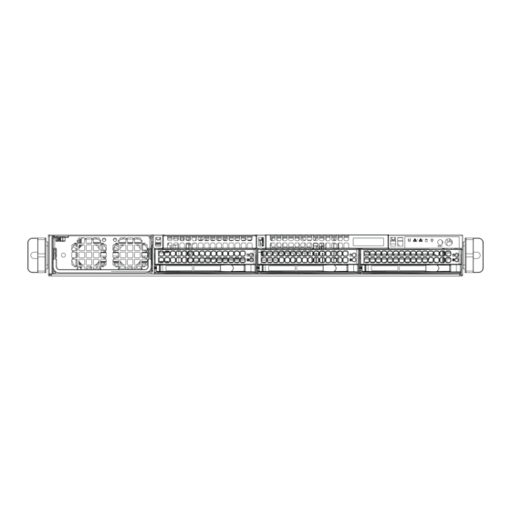
A+ SERVER 1042G-TF User's Manual Figure 6-1. Chassis: Front and Rear Views Power Supply Control Panel Hot-Swap Drive Bays (3) PS2 Keyboard/ Mouse Ports Ports PCI Slot Dedicated IPMI Ports Port Port LAN Port Control Panel The control panel (located on the front of the chassis) must be connected to the JF1 connector on the serverboard to provide you with system status indications. -
Page 66: System Fan Failure
Chapter 6: Advanced Chassis Setup System Fan Failure Fan speed is controlled by system temperature via a BIOS setting. If a fan fails, the remaining fans will ramp up to full speed. Replace any failed fan at your earliest convenience with the same type and model (the system can continue to run with a failed fan). -
Page 67: Drive Bay Installation/Removal
Peripheral Drives: The SC818TS chassis includes space for a variety of peripheral drive options, including a 2.5" hard disk drive, DVD-ROM or fl oppy drive. For a complete listing of peripheral drive options, visit the Supermicro web site at: http://www.supermicro.com/products/chassis/1U/818/SC818TS-1400.cfm... - Page 68 Chapter 6: Advanced Chassis Setup Figure 6-3. Removing a Hard Drive Carrier...
- Page 69 A+ SERVER 1042G-TF User's Manual Installing a Hard Drive to the Hard Drive Carrier Remove the two screws securing the dummy drive to the carrier. Remove the dummy drive from the carrier. Install a new drive into the carrier with the printed circuit board side facing downward so that the mounting holes align with those in the carrier.
-
Page 70: Peripheral Drive Installation
Chapter 6: Advanced Chassis Setup Figure 6-5. Installing/Removing the Carrier Next to the Power Supply Peripheral Drive Installation Installing or Replacing a Peripheral Drive Unplug the main power cord to the chassis. Unplug the power and data cables from the motherboard and/or backplane. If you are adding a new drive, fi... -
Page 71: Installing The Air Shroud
A+ SERVER 1042G-TF User's Manual Installing the Air Shroud Air shrouds concentrate airfl ow to maximize fan effi ciency. The air shroud for the SC818TS chassis does not require screws to set up. Installing the Air Shroud Position the air shroud in the chassis as illustrated above. Align the notch (A) on the air shroud with the pin (B) on the add-on card bracket. - Page 72 Chapter 6: Advanced Chassis Setup Figure 6-6. Installing the Air Shroud...
-
Page 73: Power Supply
Power Supply Failure If the power supply module fails, the system will shut down and you will need to replace the module. Replacements can be ordered directly from Supermicro (see contact information in the Preface). As there is only one power supply module in the system, power must be completely removed from the server before removing and replacing the power supply for whatever reason. -
Page 74: Chapter 7 Bios
Chapter 7: BIOS Chapter 7 BIOS Introduction This chapter describes the AMIBIOS™ Setup utility for the H8QGi+-F serverboard. The AMI ROM BIOS is stored in a fl ash chip and can be easily upgraded using a fl oppy disk-based program. Note: Due to periodic changes to the BIOS, some settings may have been added or deleted and might not yet be recorded in this manual. -
Page 75: Main Menu
A+ SERVER 1042G-TF User's Manual Main Menu When you fi rst enter AMI BIOS Setup Utility, you will see the Main Menu screen. You can always return to the Main Menu by selecting the Main tab on the top of the screen with the arrow keys. - Page 76 Chapter 7: BIOS Hit 'DEL' Message Display Use this option to Enable or Disable the "Press DEL to run setup" message in POST. Interrupt 19 Capture Select Enabled to allow ROMs to trap Interrupt 19. The options are Enabled and Disabled. Restore on AC Power Loss This sets the action that occurs when an AC power loss occurs.
- Page 77 A+ SERVER 1042G-TF User's Manual CPU DownCore Mode This option sets the CPU DownCore Mode for your system. If you change this option then a cold reset is required. Options include Auto Mode, Maximum Core Level, No Leveling, 2 Cores, 4 Cores, 6 Cores, 8 Cores, 10 Cores and 12 Cores.
- Page 78 Chapter 7: BIOS ECC Confi guration ECC Mode This submenu sets the level of ECC protection. Options include Disabled, Basic, Good, Super, Max and User. Selecting User activates the other op- tion for user setting. Note: The "Super" ECC mode dynamically sets the DRAM scrub rate so all of memory is scrubbed in 8-hours.
- Page 79 A+ SERVER 1042G-TF User's Manual Legacy USB Support Select "Enabled" to enable the support for USB Legacy. Disable Legacy support if there are no USB devices installed in the system. "Auto" disabled Legacy support if no USB devices are connected. The options are Disabled, Enabled and Auto. ...
- Page 80 Chapter 7: BIOS Use this value if the IDE disk drive support cannot be determined. Select 0 to allow BIOS to use PIO mode 0, which has a data transfer rate of 3.3 MBs. Select 1 to allow BIOS to use PIO mode 1, which has a data transfer rate of 5.2 MBs.
- Page 81 A+ SERVER 1042G-TF User's Manual PCI/PNP Confi guration Clear NVRAM Select Yes to clear NVRAM during boot-up. The options are Yes and No. Plug & Play O/S Select Yes to allow the OS to confi gure Plug & Play devices. (This is not required for system boot if your system has an OS that supports Plug &...
- Page 82 Chapter 7: BIOS Serial 2 Address This option specifi es the base I/O port address and Interrupt Request address of serial port 2. Select "Disabled" to prevent the serial port from accessing any system resources. When this option is set to "Disabled", the serial port physically becomes unavailable.
- Page 83 A+ SERVER 1042G-TF User's Manual Sredir Memory Display Delay Use this setting to set the delay in seconds to display memory information. Options are No Delay, 1 sec, 2 secs and 4 secs. Hardware Health Confi guration CPU Overheat Temperature This setting allows you to specify the type of alarm for CPU overheating.
- Page 84 Chapter 7: BIOS ACPI APIC Support Determines whether to include the ACPI APIC table pointer in the RSDT pointer list. The available options are Enabled and Disabled. Headless Mode Use this setting to enable or disable headless operation mode through ACPI.
-
Page 85: Security Settings Menu
A+ SERVER 1042G-TF User's Manual MAC Address In the fi eld provided here enter the MAC address in the hex form of xx.xx. xx.xx.xx.xx with xx in hex form only. The current MAC address in the BMC is shown. ... -
Page 86: Boot Settings Menu
Chapter 7: BIOS Change User Password Select this option and press <Enter> to access the sub menu, and then type in the password. Boot Sector Virus Protection This option is near the bottom of the Security Setup screen. Select "Disabled" to deactivate the Boot Sector Virus Protection. -
Page 87: Exit Menu
A+ SERVER 1042G-TF User's Manual Network Drives This feature allows you to specify the boot sequence from the list of available network drives. A device that is in parenthesis has been disabled in the corresponding type menu. Retry Boot Device This setting allows you to enable or disable auto retry of all boot devices. -
Page 88: Appendix A Bios Error Beep Codes
Appendix A: BIOS Error Beep Codes Appendix A BIOS Error Beep Codes During the POST (Power-On Self-Test) routines, which are performed each time the system is powered on, errors may occur. Non-fatal errors are those which, in most cases, allow the system to continue the boot-up process. - Page 89 A+ SERVER 1042G-TF User's Manual Notes...
-
Page 90: Appendix B Installing Windows
Settings before you install the Windows OS and other software drivers. To confi gure RAID settings, please refer to RAID Confi guration User Guides posted on our web site at www.supermicro.com/support/manuals. Note: The following OS installation instructions are written for the Windows XP/2003 OS only. -
Page 91: B-2 Installing Windows To A Non-Raid System
fi les and then continue with the Windows installation. After the installation has completed, the system will automatically reboot. Insert the Supermicro Setup CD that came with your system into the CD- ROM drive during system boot and the main screen will display. -
Page 92: Appendix C System Specifi Cations
Appendix C: System Specifi cations Appendix C System Specifi cations Processors Quad AMD Opteron 6100 series (AMD Socket G34) processors Note: please refer to our website for details on supported processors. Chipset One AMD SR5690 chipset and one SP5100 Southbridge chipset BIOS 16 Mb AMIBIOS SPI Flash ROM Memory Capacity... - Page 93 A+ SERVER 1042G-TF User's Manual Serverboard H8QGi+-F (Proprietary form factor) Dimensions: 16.48" x 13" (418 x 330 mm) Chassis SC818TS-1400LPBP (1U rackmount) Dimensions: (WxHxD) 17.2 x 1.7 x 28.2 in. (437 x 43 x 716 mm) Weight Gross (Bare Bone): 43 lbs. (19.5 kg.) System Cooling Four sets of 4-cm counter-rotating cooling fans (fan speed controlled by BIOS setting)
- Page 94 Appendix C: System Specifi cations Regulatory Compliance Electromagnetic Emissions: FCC Class A, EN 55022 Class A, EN 61000-3-2/- 3-3, CISPR 22 Class A Electromagnetic Immunity: EN 55024/CISPR 24, (EN 61000-4-2, EN 61000-4-3, EN 61000-4-4, EN 61000-4-5, EN 61000-4-6, EN 61000-4-8, EN 61000-4-11) Safety: CSA/EN/IEC/UL 60950-1 Compliant, UL or CSA Listed (USA and Canada), CE Marking (Europe) California Best Management Practices Regulations for Perchlorate Materials:...
- Page 95 A+ SERVER 1042G-TF User's Manual (continued from front) The products sold by Supermicro are not intended for and will not be used in life support systems, medical equipment, nuclear facilities or systems, aircraft, aircraft devices, aircraft/emergency com- munication devices or other critical systems whose failure to perform be reasonably expected to result in signifi...
Need help?
Do you have a question about the Altus 1804i and is the answer not in the manual?
Questions and answers