Table of Contents
Advertisement
Quick Links
MOLEAER NEO-N™
NANOBUBBLE GENERATOR
OWNERS MANUAL
IMPORTANT SAFETY INSTRUCTIONS
READ AND FOLLOW ALL INSTRUCTIONS
SAVE THESE INSTRUCTIONS
CUSTOMER SERVICE / TECHNICAL SUPPORT
If you have questions about ordering
Moleaer, Inc. replacement parts and products,
please use the following contact information:
CUSTOMER SERVICE:
Monday to Friday: 8:00 a.m. to 5:00 p.m. PST
Phone: +1 (424) 558-3567
Email:
mailto:info@moleaer.com
WEBSITE:
www.moleaer.com
Advertisement
Chapters
Table of Contents
Troubleshooting

Related Manuals for MOLEAER NEO-N S2


Summary of Contents for MOLEAER NEO-N S2
- Page 1 CUSTOMER SERVICE / TECHNICAL SUPPORT If you have questions about ordering Moleaer, Inc. replacement parts and products, please use the following contact information: CUSTOMER SERVICE: Monday to Friday: 8:00 a.m. to 5:00 p.m. PST Phone: +1 (424) 558-3567 Email: mailto:info@moleaer.com MOLEAER NEO-N™...
- Page 3 PRODUCT INTRODUCTION ..............3-1 INSTALLATION INSTRUCTIONS ............4-1 STARTUP GUIDE ................. 5-1 OPERATION MANUAL ................ 6-1 CLEAN IN PLACE (CIP) INSTRUCTIONS .......... 7-1 KITS AND SPARE PARTS ..............8-1 COMPONENT INFORMATION ............9-1 INSPECTION AND PREVENTIVE MAINTENANCE ......10-1 www.moleaer.com...
- Page 4 www.moleaer.com...
- Page 5 WARRANTY INFORMATION LIMITED WARRANTY WARRANTY INFORMATION Section 1 Contents Limited Warranty ................1-2 European Declaration of Conformity ..........1-3 www.moleaer.com...
- Page 6 INFRINGEMENT. Claims; Exclusive Remedy Any warranty claim must be made to Moleaer in writing within 10 days of discovery of the alleged defect. After obtaining prior written authorization from Moleaer, Buyer shall return all allegedly defective Goods, freight pre- paid, for examination by Moleaer. If Moleaer finds that the Goods are defective and covered by the warranty, Moleaer’s sole obligation shall be, at Moleaer’s option, to repair or replace the Goods, or to refund the...
- Page 7 Directive(s). This EU declaration of Conformity is only valid when published as part of the Moleaer, Inc. installation and operating instructions. (Publication numbers; 01/02/03/04/05/06 2019V1/2/3/4/5/6)
- Page 8 SAFETY INSTRUCTIONS IMPORTANT NOTICE SAFETY INSTRUCTIONS Section 2 Contents Important Notice ................2-2 Attention Installer ................2-2 Attention User .................. 2-2 Risk of Electrical Shock ............2-2 General Warnings ..............2-2 Suction Entrapment Hazard ............2-3 www.moleaer.com...
- Page 9 Attention User This manual contains important information that will help you in operating and maintaining this product. Please retain it for future reference. Additional information and resources related to Moleaer products are available at https://www.moleaer.com/portal READ AND FOLLOW ALL INSTRUCTIONS. SAVE THESE INSTRUCTIONS.
- Page 10 / her body over or near the pump or isolation valves. This installation should allow the user enough space to stand clear of the system and pump during system startup, shutdown, or servicing of the system. This generator has been evaluated for use with water only. www.moleaer.com...
- Page 11 SYSTEM VALVES IN THE “OPEN” POSITION TO ALLOW WATER TO FLOW FREELY FROM THE TANK AND BACK TO THE TANK. STAND CLEAR OF ALL EQUIPMENT AND START THE PUMP. IMPORTANT: OBSERVE SYSTEM PRESSURE GAUGES AND BE SURE IT IS NOT HIGHER THAN THE PRE-SERVICE CONDITION. www.moleaer.com...
-
Page 12: Table Of Contents
Introduction ..................3-2 Additional Documents ..............3-2 Equipment General Arrangement ............ 3-3 Datasheets ..................3-4 NEO-N 50 HZ Standard ............3-4 NEO-N 50 HZ with Oxygen ............3-5 NEO-N 60 HZ Standard ............3-6 NEO-N 60 HZ with Oxygen ............3-7 www.moleaer.com... -
Page 13: Introduction
3. GAD: General arrangement of the unit, dimensions and information about the inlet, outlet, and customer points of connection port sizes. 4. 3D CAD models: 3D CAD models of the units are available on request. Contact Moleaer. 5. Installation Manual: Provides general instructions to install the product. -
Page 14: Equipment General Arrangement
PRODUCT INTRODUCTION EQUIPMENT GENERAL ARRANGEMENT Equipment General Arrangement Product Variants General Features Standard Off-board gas, No compressor. Onboard Oxygen Generator On-board O generator, one compressor www.moleaer.com... -
Page 15: Datasheets
Note 3: Flange adapter kits for inlet and discharge connections come standard for all units. Note 4: When using oxygen, Moleaer recommends CGA inlet 540, outlet 9/16” - 18RH pressure regulator with delivery range of 5 - 150 PSI (0.34 - 10.3 bar). -
Page 16: Neo-N 50 Hz With Oxygen
Note 1: Maximum Gas Pressure does not represent gas pressure indicated on the machine during normal operation. Note 2: Recommended gas flow at max liquid flow and standard conditions: 20 °C, and 1.013 bar. Note 3: Flange adapter kits for inlet and discharge connections come standard for all units. www.moleaer.com... -
Page 17: Neo-N 60 Hz Standard
Note 3: Flange adapter kits for inlet and discharge connections come standard for all units. Note 4: When using oxygen, Moleaer recommends CGA inlet 540, outlet 9/16” - 18RH pressure regulator with delivery range of 5 - 150 PSI (0.34 - 10.3 bar). -
Page 18: Neo-N 60 Hz With Oxygen
Note 1: Maximum Gas Pressure does not represent gas pressure indicated on the machine during normal operation. Note 2: Recommended gas flow at max liquid flow and standard conditions: 36% relative humidity, 68 °F, and 14.7 psia. Note 3: Flange adapter kits for inlet and discharge connections come standard for all units. www.moleaer.com... - Page 19 Neo-N Frame Dimensions and Component Descriptions ..4-11 Suction Piping Installation ............4-12 Discharge Piping Installation ........... 4-12 CIP/Sampling Valve and Isolation Valve Installation (Optional) ........4-13 Connect Power to Control Box ..........4-13 Single-Phase Wiring ..........4-13 Three-Phase Wiring ........... 4-14 Ground Connection ............ 4-15 www.moleaer.com...
-
Page 20: General Information
Refer to installation manual (available upon request). Parts and Accessories The parts shown in Table 1 below are offered as accessories available for purchase with all Neo-N standard products. Table 1: Regulator Kit Parts List Image Quantity Part Description Regulator High Pressure Oxygen Hose www.moleaer.com... -
Page 21: Location Requirements
Use the schematic shown in Figure 1 for mounting hole placement. Figure 1: Plan view of Neo-N frame showing mounting hole placement. Failure to install the Neo-N within the limits specified in this document may void the system warranty and result in poor nanobubble production and pump cavitation. www.moleaer.com... -
Page 22: Power Requirements
INSTALLATION INSTRUCTIONS POWER REQUIREMENTS Power Requirements Table 2: Power Requirements Unit Version Voltage Phase Amps Pump Manufacturer NEO-N S2* Off Board Gould Lowara Pacer Pentair NEO-N S2* On Board Gould Oxygen Lowara Pacer 10.3 Pentair NEO-N S3* On Board Gould... - Page 23 Pump Manufacturer 18.9 Pentair Lowara 16.3 16.2 NEO-N S5* On Board Gould Oxygen Lowara 10.0 Hayward NEO-N S5* On Board 10.0 Gould Oxygen 10.9 Lowara 11.9 Hayward * Refer to order form or pump name plate to verify power requirements. www.moleaer.com...
-
Page 24: Piping Connections
3’’ (US) 3’’ (US) 1’’ to 2’’ (US) 3’’ FLANGE-GOULDS 3’’ (US) 3.0’’ (US) S5 NEO-N 90 mm (EU) 90 mm 32 mm to 63 mm (EU) DN80 mm FLANGE-LOWARA 90 mm (EU) 90 mm (EU) (EU) 2-1/2’’ NPT-HAYWARD www.moleaer.com... -
Page 25: Installation Guidelines
40 to 140 PSI (2.75 to 9.65 bar) and adjust the flow using the rotameter knob to the recommended values on Table 4. DO NOT EXCEED 140 PSIG (9.65 BAR) SUPPLY GAS PRESSURE. Excessive pressure may void warranty and compromise gas seals resulting in a sudden drop in backpressure. www.moleaer.com... -
Page 26: Neo-N Flooded Suction Installation
The pipe between the tank and the Neo-N should fill with water via gravity. Moleaer highly recommends installing clean-in-place (CIP)/sampling valves and isolation valves upstream and downstream of the Neo-N, especially in instances of unclean water. Refer to Figure 8 for Neo-N frame dimensions and suction and discharge fitting locations. -
Page 27: Neo-N Suction Lift Installation
The pipe between the tank and the Neo-N will not fill with water without the use of the pump. Moleaer recommends the check valve size is double the size of the suction pipe. -
Page 28: Neo-N Multiple Tank Set Up Installation Example
The Neo-N can be connected to treat the water in multiple tanks. Refer to Figure 6 for multiple tank installation. Figure 6: Isometric view of Neo-N suction and discharge layout in a multiple tank installation. NOTE: Contact your salesperson for further information on multiple tank installations. www.moleaer.com 4-10... -
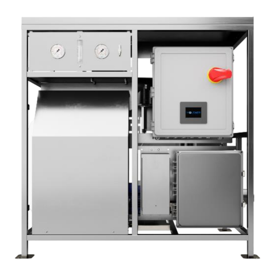
Page 29: Neo-N Frame Dimensions And Component Descriptions
INSTALLATION INSTRUCTIONS INSTALLATION GUIDELINES Neo-N Frame Dimensions and Component Descriptions Figure 7: Back and front view of Neo-N with component descriptions. Figure 8: Neo-N with suction and discharge connection locations. www.moleaer.com 4-11... -
Page 30: Suction Piping Installation
For suction lift installations, install a PVC swing check valve on the suction pipe. Install the check valve above the maximum liquid level of the tank to maintain accessibility for inspection and service. Moleaer recommends the check valve size to be double the size of the suction pipe. -
Page 31: Cip/Sampling Valve And Isolation Valve Installation (Optional)
S3 models come in single-phase and three-phase models while all Neo-N S5 models are three-phase. Before connecting power, verify the voltage, phase and amps requirements of your unit. Neo-N S2 and S3 models come in single-phase and three-phase models while all Neo-N S5 models are three-phase. -
Page 32: Three-Phase Wiring
Verify that the Neo-N is a three-phase model by checking the number of wires coming out of the main disconnect. In a three-phase model, there will be three wires coming out of this disconnect, shown in the orange circle in Figure 12. Figure 12: Output terminal connections on the main disconnect wired for three-phase. www.moleaer.com 4-14... -
Page 33: Ground Connection
If it does not match, then reverse any two of the three power leads from the control box. Ground Connection Figure 14: Ground connection blocks. WARNING: Ensure that the ground wire from the power cable is connected to the grounding blocks inside the enclosure. www.moleaer.com 4-15... - Page 34 STARTUP GUIDE QUICK STARTUP STARTUP GUIDE Section 5 Contents Quick Startup ................... 5-2 Flooded Suction Applications: Pump Priming Instructions ..5-2 Suction Lift Applications: Pump Priming Instructions....5-4 Suction and Discharge Operation ........... 5-6 Operating Parameter Ranges ............5-7 www.moleaer.com...
-
Page 35: Quick Startup
Step 1. Open the intake and discharge valves to flood piping. Intake and Discharge Isolation Valves Intake and Discharge CIP/Sampling Valves Step 2. Open the bleed valve on the faceplate to release any air trapped in the piping. Bleed Valve www.moleaer.com... - Page 36 On the touch screen*, tap the MODE button and select MANUAL. * Touch screen will automatically power OFF after 15 minutes of inactivity. Tap the touch screen to turn ON display. Step 5. Tap START on the main screen to start the pump in MANUAL mode. www.moleaer.com...
-
Page 37: Suction Lift Applications: Pump Priming Instructions
Remove the lid from the pump basket and fill the basket with water using a bucket or hose. Fill the basket until the water level is above the suction opening. Replace the basket lid. Step 3. Turn on the main power using the disconnect button on the Neo-N power panel. Main Power Disconnect Button www.moleaer.com... - Page 38 A large air pocket or large bubbles should not be visible in the strainer basket. If large bubbles or an air pocket are visible in the strainer basket, there is a suction pipe leak. Turn OFF Neo-N and check the suction pipe for leaks and ensure all pipe connections are airtight. www.moleaer.com...
-
Page 39: Suction And Discharge Operation
Figure 15: Bubble pattern for a proper installation Note: If bubbles are consistently larger than the size of a pea, contact a Moleaer technical service representative by filling out a customer support form at https://www.moleaer.com/portal. -
Page 40: Operating Parameter Ranges
0 to 3.91 lpm) 0 to 4.48 lpm US and EU Note: If the Neo-N unit is consistently operating outside of the ranges shown in Table 4, contact a Moleaer technical service representative by filling out a customer support form at https://www.moleaer.com/portal. www.moleaer.com... - Page 41 Capacitor Replacement ............6-10 Compressor Troubleshooting ............6-11 Winterizing ..................6-11 Outdoor Nanobubble Cold Weather Bulletin ......6-11 Preparation For Above Water-Freezing Temperature ......6-12 Preparation For Below Water-Freezing Temperature ......6-12 Cleaning and Sanitizing ..............6-12 System Troubleshooting ..............6-13 www.moleaer.com...
-
Page 42: Gas Compression System
GAS COMPRESSION SYSTEM Gas Compression System The Moleaer Neo-N Nanobubble Generator Standard is designed for use with compressed oxygen. Inert gases and CO2 may be used on the Standard Neo-N variant within the operating pressure and flow of the product. - Page 43 In either case, a check valve just above the intake screen is required to prevent backflow. Moleaer recommended check valve size is double the size of the suction pipe. 2. Turn on the main power disconnect on the power panel. Start and test pump in manual mode with all valves opened, check piping for visible leaks.
- Page 44 OPERATION MANUAL NANOBUBBLE GENERATOR OPERATION NOTE: The main flowmeter is located on the front side of the Neo-N. The oxygen generator flowmeter and knob are located on the left side of the oxygen generator enclosure. Main Flowmeter Oxygen Generator Flowmeter www.moleaer.com...
-
Page 45: Programable Logic Controller (Plc) Operation
The whole system should be checked to find the reason for the LOW ALARM PRESSURE. Most common issues are: • Pressure Switch: Check the setup of the pressure Switch. • Pump does not prime correctly: Check the check valve or any leakage in suction pipe. www.moleaer.com... -
Page 46: Operation Mode Screen
3. In TIMER SCHEDULE mode, the system will start when the START button the MAIN MENU screen is pressed. It will run for the RUN TIME set on the timers screen and then stop for the OFF time set on the TIMERS screen. Minimum OFF time is 10 minutes. www.moleaer.com... -
Page 47: Timers Screen
40. The system will run up the D.O. SETPOINT while in D.O. SCHEDULE mode, which would need to be set on the OPERATION MODE screen and will startup after the START button is pressed on the MAIN MENU screen. www.moleaer.com... -
Page 48: Calibration Screen
3. If the unit is operated at maximum duties in a clean, 65 °F to 75 °F (18 °C to 24 °C) ambient environment with 35% relative humidity, complete first inspection and maintenance after 4,000 hours/6 months of operation. Earlier maintenance may be required depending upon the environment. www.moleaer.com... -
Page 49: Compressor Independent Shutdown
8. Use cylinder screws with washers to attach cylinder to bracket. Tighten screws only until they are finger tight. 9. Move pistons to top dead center position. Adjust each cylinder flush with top of piston. 10. Torque cylinder screws to 150 to 160 in-lbs (17 to 18 N•m). 11. Replace valve components in original order. www.moleaer.com... -
Page 50: Capacitor Replacement
19. Check that all external accessories such as relief valves and gauges are attached to the cover and are not damaged before reoperating the product. Capacitor Replacement Compressor capacitor must be replaced per the preventative maintenance interval. The preventative maintenance kit contains the capacitor. www.moleaer.com 6-10... -
Page 51: Compressor Troubleshooting
PSI but Will Not 2. Replace the check valve. Start Under Pressure 3. If unit does not operate after following the steps above, contact Moleaer. Motor Starts 1. Follow the independent compressor shutdown procedure in the Gas Compressors section. Intermittently 2. -
Page 52: Preparation For Above Water-Freezing Temperature
In some instances, if large solids are allowed to pass into the generator, blockages can occur. The best indication for cleaning is a rise in gas pressure. Moleaer recommends that a Clean-in-Place (CIP) be performed at least every month if not more frequently depending on the local conditions. -
Page 53: System Troubleshooting
If debris cannot be removed, complete the following steps: Remove impeller reverse screw and O-ring. Remove, clean, and reinstall impeller. Reinstall anti-spin bolt. Reinstall diffuser and O-ring. Reinstall motor and seal plate into volute. Reinstall hardware around seal plate and volute and tighten securely. www.moleaer.com 6-13... - Page 54 Transfer • • Delta gas pressure out of range. Clean rotameter, gas lines, and fittings. • • Follow specified “clean-in-place” procedures for Excessive moisture and / or contaminant in the gas line. internal cleaning. • Internal system fouling. www.moleaer.com 6-14...
- Page 55 NPSH too low - excessive suction Repair or replace motor if damaged. lift or losses. • Open discharge valve or reduce restriction. • Incorrect rotation (three phase only). • Defective motor. • Discharge, suction plugged, or valve closed. • Impeller worn or plugged. www.moleaer.com 6-15...
- Page 56 CLEAN IN PLACE (CIP) INSTRUCTIONS CLEAN-IN-PLACE PROCEDURES CLEAN IN PLACE (CIP) INSTRUCTIONS Section 7 Contents Clean-In-Place Procedures ............. 7-2 Parts Required ................7-2 Vertical Alignment Nanobubble Generator Cleaning Procedure ..........7-3 www.moleaer.com...
- Page 57 Syringe Kit Assembly Instructions 1. Hand Screw the Plastic Coupling into the Air Fitting. Make Sure it Gets Hand Tight. 2. Insert the Tube into the Air Fitting. 3. Insert the coupling into the syringe and press firmly. 4. Final assembly. www.moleaer.com...
- Page 58 4. Prepare the syringe with cleaning solution. 5. Inject about 25 ml of cleaning solution into the nanobubble generator as shown in the picture. Keep injecting the solution until it comes out from the other end. Clean the extra solution with a piece of cloth. www.moleaer.com...
- Page 59 Repeat 3 times. Generally, after 3 flushes, the remainder of the solution is very small and can be left inside the system. 8. Reconnect the air fitting tube to the air fittings of the nanobubble generator. 9. Turn the system on. 10. Run the system for 10 minutes. Gas pressure should decrease, and gas flow should improve. www.moleaer.com...
- Page 60 KITS AND SPARE PARTS PREVENTATIVE MAINTENANCE KITS KITS AND SPARE PARTS Section 8 Contents Preventative Maintenance Kits ............8-2 Emergency Spare Parts ..... Error! Bookmark not defined. US Models ........Error! Bookmark not defined. EU Models ........Error! Bookmark not defined. www.moleaer.com...
- Page 61 Maintenance Kit, 2 years/12,000 hours AirSep Topaz Ultra 30K0-004 Maintenance Kit, 4 years/30,000 hours AirSep Topaz Ultra - Includes 30K0-003 30K0-006 Maintenance kit, 2 years, NEO-N S2 with onboard Oxygen generator. Includes 30K0-001 30K0-007 Maintenance kit, 4 years, NEO-N S2 with onboard Oxygen generator. Includes 30K0-002 30K0-008 Maintenance kit, 2 years, NEO-N S3 &...
- Page 62 Mechanical Pressure Switches............9-43 Technical Data ................ 9-43 Optical Dissolved Oxygen Probe ........... 9-45 Solenoid Valve ................9-53 Back Pressure Regulator ............... 9-56 EZ-Touch Mini 4 PLC ..............9-61 Safety ..................9-61 Changing the Battery .............. 9-63 Troubleshooting ..............9-65 www.moleaer.com...
-
Page 63: Eu Lowara Pumps Specifications Sheets
Most Neo-N EU units are equipped with Lowara centrifugal flooded suction pumps. Always check your unit’s pump model and brand before referring to this section. For all other pumps, contact Moleaer for specifications. NOTE: A flooded suction in a centrifugal pump is where liquid originates. The liquid is held at a level above the suction port of the pump and allows liquid to arrive at the pump through gravity. -
Page 64: Eu S2 Neo-N Pump Information - Lowara
COMPONENT INFORMATION EU LOWARA PUMPS SPECIFICATIONS SHEETS EU S2 Neo-N Pump Information - Lowara www.moleaer.com... - Page 65 COMPONENT INFORMATION EU LOWARA PUMPS SPECIFICATIONS SHEETS www.moleaer.com...
-
Page 66: Eu S3 Neo-N Pump Information - Lowara
COMPONENT INFORMATION EU LOWARA PUMPS SPECIFICATIONS SHEETS EU S3 Neo-N Pump Information - Lowara www.moleaer.com... - Page 67 COMPONENT INFORMATION EU LOWARA PUMPS SPECIFICATIONS SHEETS www.moleaer.com...
-
Page 68: Eu S5 Neo-N Pump Information - Lowara
COMPONENT INFORMATION EU LOWARA PUMPS SPECIFICATIONS SHEETS EU S5 Neo-N Pump Information - Lowara www.moleaer.com... - Page 69 COMPONENT INFORMATION EU LOWARA PUMPS SPECIFICATIONS SHEETS www.moleaer.com...
-
Page 70: Us Neo-N Gould Pumps Performance Specifications
Most Neo-N US units are equipped with Gould centrifugal flooded suction pumps. Always check your unit’s pump model and brand before referring to this section. For all other pumps, contact Moleaer for specifications. NOTE: A flooded suction in a centrifugal pump is where liquid originates. The liquid is held at a level above the suction port of the pump and allows liquid to arrive at the pump through gravity. -
Page 71: S2 Neo-N Pump Information - Gould
COMPONENT INFORMATION US NEO-N GOULD PUMPS PERFORMANCE SPECIFICATIONS S2 Neo-N Pump Information - Gould www.moleaer.com 9-10... - Page 72 COMPONENT INFORMATION US NEO-N GOULD PUMPS PERFORMANCE SPECIFICATIONS www.moleaer.com 9-11...
-
Page 73: S3 Neo-N Pump Information - Gould
COMPONENT INFORMATION US NEO-N GOULD PUMPS PERFORMANCE SPECIFICATIONS S3 Neo-N Pump Information - Gould www.moleaer.com 9-12... - Page 74 COMPONENT INFORMATION US NEO-N GOULD PUMPS PERFORMANCE SPECIFICATIONS www.moleaer.com 9-13...
-
Page 75: S5 Neo-N Pump Information - Gould
COMPONENT INFORMATION US NEO-N GOULD PUMPS PERFORMANCE SPECIFICATIONS S5 Neo-N Pump Information - Gould www.moleaer.com 9-14... - Page 76 COMPONENT INFORMATION US NEO-N GOULD PUMPS PERFORMANCE SPECIFICATIONS www.moleaer.com 9-15...
-
Page 77: Gas Compressor Operation Manual
GAS COMPRESSOR OPERATION MANUAL Gas Compressor Operation Manual 86R and 87R Series Rocking Piston Oil-Less Pump GAST PART NO. 70-6953 (REV. A) Gast / Jun-Air AIR COMPRESSOR ROCKING PISTON OIL-LESS PUMPS Operation and Maintenance Manual 86R and 87R Series Single Cylinder www.moleaer.com 9-16... - Page 78 Remove plus from the IN and OUT ports. Connect with pipe and fittings that are the same size or larger than the product’s threaded ports. Be sure to connect the intake and exhaust plumbing to the correct inlet and outlet ports. Ports will not support plumbing. www.moleaer.com 9-17...
- Page 79 Check that the voltage is correct for motor and that motor is turning in the proper direction. Check the plug, cord and switch for damage. If so equipped, the thermal protection switch has tripped, the motor can restart after cooling. www.moleaer.com 9-18...
- Page 80 4. Check filter felt. Replace felt if it is covered with contamination or shows signs of increasing differential pressure. 5. Reinstall felt and filter cover. Check that all external accessories, such as relief valves and gauges are attached to cover and are not damaged before re-operating product. www.moleaer.com 9-19...
- Page 81 2. Disconnect air supply and vent all air lines to release pressure or vacuum. 3. Mark the orientation of the ports so cover will be reinstalled correctly. 4. Remove screws from the head of the pump. Remove the head of the pump. Mark orientation of valve plate(s). remove valve plate(s). www.moleaer.com 9-20...
- Page 82 Check that all external accessories, such as relief valves and gauges, are not damaged before re-operating product. If the pump still does not product proper vacuum or pressure, send unit to a Gast Authorized Service Facility for repair. www.moleaer.com 9-21...
-
Page 83: Datasheet
COMPONENT INFORMATION GAS COMPRESSOR OPERATION MANUAL Datasheet www.moleaer.com 9-22... -
Page 84: 86R And 87R Series Rocking Piston Oil-Less Pump Troubleshooting Chart
Bent / damaged valves - replace. Damaged / worn cup - replace. Leaky hose. Leaky check valve. Plugged vacuum or pressure line. Low voltage. Leaky relief valve. Motor not wired correctly - check wiring diagram / line voltage. www.moleaer.com 9-23... -
Page 85: Airsep Oxygen Generator
Do not position the generator in an area that makes it difficult to disconnect the power. To prevent fire or electrical shock, locate the oxygen generator indoors away from rain or any other type of moisture. www.moleaer.com 9-24... -
Page 86: System Description
The molecular sieve does not normally require replacement when maintained and used according to this instruction manual. Contact AirSep Corporation for a detailed flow diagram, an electrical schematic, and specifications for the oxygen generator. www.moleaer.com 9-25... -
Page 87: Components Description
Refer to FLOW SCHEMATIC in this instruction manual for general layout drawings and specifications. Oxygen Generator Model designation is as follows. Moleaer Product Oxygen Generator Model NEO-N S2 AirSep Topaz NEO-N S3 AirSep Topaz Ultra NEO-N S5 AirSep Topaz Ultra... - Page 88 NOTE: Increasing the flowmeter beyond the setpoint designed for the particular model can potentially cause damage to the molecular sieve and will void the warranty. Model Maximum Allowable Flow * NEO-N S2 12 CFH / 6 LPM NEO-N S3 21 CFH/ 10 LPM...
- Page 89 The cycle pressure gauge indicates the pressure inside the sieve beds. NOTE: The cycle gauge does not indicate the pressure set by the pressure regulator. The oxygen pressure gauge on the right side of the enclosure indicates the pressure set by the pressure regulator. www.moleaer.com 9-28...
- Page 90 NOTE: Changing the regulator setpoint in any way can potentially cause damage to the molecular sieve and will void the warranty. Exhaust Muffler The exhaust muffler allows waste gas to exit the adsorbers. Hour Meter The hour meter indicates the total number of hours that the unit cycles. www.moleaer.com 9-29...
-
Page 91: System Operation
Using the oxygen generator at flows higher than 15% above those specified in the Topaz and Topaz Ultra Technical Data section of this manual will result in the likely contamination of the molecular sieve beds. This damage is not covered under the standard warranty. www.moleaer.com 9-30... -
Page 92: Maintenance
Check performance of solenoid valves. Rebuild or replace, as necessary. * If product oxygen does not meet specifications, refer to Troubleshooting in this section. Each Neo-N unit is supplied with one spare gross particulate filter. www.moleaer.com 9-31... -
Page 93: Cleaning The Gross Particulate Filter
6. Rinse the filter thoroughly and remove excess water with a soft, absorbent towel. 7. Allow the filter to dry, and then store it in a clean location. Alternate the clean filter with the filter on the unit each time you perform this procedure. www.moleaer.com 9-32... -
Page 94: Cleaning The Enclosure
1-800-320-0303. Outside the USA or Canada, call 716-691-0202. Send fax inquiries anytime to 716-691-1255. Address written inquiries to: AirSep Corporation 260 Creekside Drive Buffalo, NY 14228-2075 USA Attention: Commercial Product Service Department Email: cpdservice@airsep.com Visit www.airsep.com for more about their complete range of standard Oxygen Generators. www.moleaer.com 9-33... -
Page 95: Troubleshooting Chart
I to restart unit. If circuit Unexpectedly breaker immediately trips again, check Circuit breaker on I/O the wiring for any short circuit. Also, power switch tripped. check I/O power switch, circuit board, capacitor, and air compressor. Replace all defective components. www.moleaer.com 9-34... - Page 96 Disconnect main power supply, remove Faulty electrical enclosure and make sure all electrical Unit Operates, connections to cooling fan. connections, including cooling fan leads, but Air Does Not Circulate connect securely. into Unit Defective cooling fan. Replace cooling fan. www.moleaer.com 9-35...
- Page 97 Defective or worn air If maximum cycle pressure is below 179 compressor. kPa (26 psig), replace air compressor. Defective circuit board. Replace circuit board. Contaminated adsorbers. Replace adsorbers. www.moleaer.com 9-36...
- Page 98 Unexpectedly Defective solenoid Repair or replace solenoid valve(s). valve(s). Defective air compressor. Replace air compressor. Defective circuit board. Replace circuit board. Unit Operates, but I/O Power Defective I/O power Replace I/O power switch. Switch Does switch. Not Illuminate www.moleaer.com 9-37...
- Page 99 Chattering or Low voltage to valve(s). this manual. If power at inlet to unit is Buzzing Noise correct, but is low at valve(s), contact from Solenoid Moleaer. Valve(s) Defective or worn solenoid Repair or replace solenoid valve(s). valve(s). www.moleaer.com 9-38...
-
Page 100: Topaz And Topaz Ultra Technical Data
Pollution Degree Installation Category Maximum Altitude Above 2,000 m (6,562 ft) Sea Level * Nm (normal cubic meters) gas measured at one atmosphere and 0 °C. ** SCF (standard cubic foot) gas measured at one atmosphere and 70 °F. www.moleaer.com 9-39... - Page 101 Pollution Degree Installation Category Maximum Altitude Above Sea 2,000 m (6,562 ft) Level * Nm (normal cubic meters) gas measured at one atmosphere and 0 °C. ** SCF (standard cubic foot) gas measured at one atmosphere and 70 °F. www.moleaer.com 9-40...
- Page 102 COMPONENT INFORMATION AIRSEP OXYGEN GENERATOR FLOW SCHEMATIC www.moleaer.com 9-41...
- Page 103 COMPONENT INFORMATION AIRSEP OXYGEN GENERATOR 240 V, 50 HZ OR 60 HZ ELECTRICAL SCHEMATIC www.moleaer.com 9-42...
-
Page 104: Mechanical Pressure Switches
Rated Current Range 10 mA to 4 A Resistive Load, DC12/ AC12 Switching Power, DC12/AC12 100 W/ 100 VA Temperature resistance for -40 °F to +212 °F sealing materials - NBR (-40 °C to +100 °C) (diaphragm pressure switch) www.moleaer.com 9-43... - Page 105 10 g: 5 to 200 Hz sine wave; DIN EN 60068-2-6 Shock Resistance 294 m/s ; 14 ms half sine wave; DIN EN 60068-2-27 Up to IP67/IP6K9K according to manufacturer’s Protection Class specification for the respective plug-in-system only when plugged in, otherwise IP00 Weight Approximately 90 g www.moleaer.com 9-44...
-
Page 106: Optical Dissolved Oxygen Probe
The two UART wires can be cut if users do not need PC monitoring and firmware updates. Outputting temperature or pressure (depth) is also optional based on the customer requirements. The wire color might be changed and please refer to the manual attached to the probe. www.moleaer.com 9-45... - Page 107 Time between taps must be less than five seconds for a single command. No matter how long the magnet is held on the magnet are of probe, it is counted as one tap. 5. To avoid accidentally calibrating probes during measuring, the one-point calibration is set as three taps. www.moleaer.com 9-46...
- Page 108 1-point calibration for the 100% saturation can be done by the following means. NOTE: Sensor Calibration requires a sensor cap. Each unit is shipped with a DO sensor cap. Contact Moleaer if the cap is missing or lost. IN AIR-SATURATED WATER (STANDARD METHOD WITH ERROR < 0.5%).
- Page 109 4. Observe blue LED after tapping. If the blue LED blinks = the last digit of cap SN, suggesting operation success. Otherwise, repeat steps 1 through 4. NOTE: To load coefficient group 0, only do Step 1 and allow the blue LED blink to five times for confirmation. www.moleaer.com 9-48...
- Page 110 Soaking the probe in water for more than one week is a kind of customer abuse and the resulting leakage would not be covered by warranty. www.moleaer.com 9-49...
- Page 111 Input: 5 – 36 V DC. water of depth less than 50M. Consumption: average 120 mA at 5V. Materials: Ryton (PPS) body. Output: two 0-5 V lines. Cable Length: User specified. www.moleaer.com 9-50...
- Page 112 100% to 200% (10 to 20 ppm) less than +2% Greater than 200% to 300% (20 to 40 ppm): 2 to 15% Temperature +0.2 °C Pressure +0.2 kPa Calibration One point (100% cal point) in air-saturated water or water-saturated air (calibration bottle). www.moleaer.com 9-51...
- Page 113 A useful life of up to two years is feasible in optimum situations. Others Specification Description Waterproof IP68, 50 m deep or continuously soaked for a week in water depth of less than 50 m. Certifications RoHs, CE, C-Tick Materials Ryton (PPS) body Cable Length User specified www.moleaer.com 9-52...
-
Page 114: Solenoid Valve
COMPONENT INFORMATION SOLENOID VALVE Solenoid Valve MODEL #E2B19-000 SERIES E SOLENOID VALVE 2-Way, Internally Piloted, Normally Closed Solenoid Valve www.moleaer.com 9-53... - Page 115 Armature Tube Stainless steel 300 Fixed Core Stainless steel 400 Plunger Stainless steel 400 Spring Stainless steel 300 Shading Ring Copper Orifice Brass Pipe Threading Electrical Specifications Specification Description Rating NEMA 4 Inrush VA 25.0 Holding VA 14.5 www.moleaer.com 9-54...
- Page 116 COMPONENT INFORMATION SOLENOID VALVE Spare Part Numbers Specification Description Armature Tube Not available Repair Kit RK-E001 Coil / Connector C-B19 www.moleaer.com 9-55...
-
Page 117: Back Pressure Regulator
COMPONENT INFORMATION BACK PRESSURE REGULATOR Back Pressure Regulator KBP1F0D4A5A20000 www.moleaer.com 9-56... - Page 118 COMPONENT INFORMATION BACK PRESSURE REGULATOR Specifications REGULATOR DIAGRAM www.moleaer.com 9-57...
- Page 119 1 Not included in regulators with 0 to 500 psig (0 to 34.4 bar) control range. 2 Not shown. 3 Regulators with control ranges higher than 0 to 100 psig (0 to 6.8 bar) are assembled with two diaphragms. www.moleaer.com 9-58...
- Page 120 Features • Convoluted, nonperforated. • Diaphragm • Metal-to-metal diaphragm seal • Low internal volume • Two-piece cap design provides linear load on the seal. • Maximum inlet pressure • Equal to pressure control range • Pressure control ranges. www.moleaer.com 9-59...
- Page 121 Maintenance instructions for all Swagelok regulators are available from your Swagelok website. MAINTENANCE TOOLS Specially designed tools and tool kits are available to assist in the service and repair of Swagelok regulators. Contact Moleaer or your authorized Swagelok representative for more information. www.moleaer.com 9-60...
-
Page 122: Ez-Touch Mini 4 Plc
External fail-safe and / or redundant components are required to make your control system fail-safe. www.moleaer.com 9-61... - Page 123 5 to 55Hz, 2g for 2 hours in X, Y, and Z axis Shock 10g for under 12ms in the X, Y, and Z axis Noise Immunity NEMA ICS 2-230 Showering arc, ANSI C37.90a SWC; Level C Chattering Relay Test www.moleaer.com 9-62...
-
Page 124: Changing The Battery
1. Using a Philips head screwdriver, remove the four screws holding the back plate on the unit. 2. Next, make sure clips come loose (four clips are holding the back to the front.) You can loosen them with a flat head screwdriver. www.moleaer.com 9-63... - Page 125 / discretes available on a power cycle will remain intact. Data not saved to registers / discretes available during a power cycle will be lost. For information on registers / discretes available during a power cycle, please review this table. www.moleaer.com 9-64...
-
Page 126: Troubleshooting
Communication with the PC Wrong communication port Check and correct the COM port (RS232 Port settings. attributes. Error) Check if correct Serial Port (COM1) Wrong COM port assignment on assignments on the computer have the computer. been made. www.moleaer.com 9-65... - Page 127 INSPECTION AND PREVENTIVE MAINTENANCE MONTHLY INSPECTION CHECKLIST INSPECTION AND PREVENTIVE MAINTENANCE Section 10 Contents Monthly Inspection Checklist ............10-2 Preventative Maintenance Schedule ..........10-3 www.moleaer.com 10-1...
- Page 128 Note rotameter value and compare with previous readings. Adjust flow by generator using oxygen generator rotameter knob Onboard O2 Oxygen Check the fan and the inlet foam filter. Follow manual instructions to clean generator generator air the foam filter circulation www.moleaer.com 10-2...
- Page 129 INSPECTION AND PREVENTIVE MAINTENANCE PREVENTATIVE MAINTENANCE SCHEDULE Preventative Maintenance Schedule Moleaer offers preventative maintenance kits that include all replacement components as noted in the below table. Schedule Description Day 1 Perform monthly inspection Week 1 Perform monthly inspection Week 2...
- Page 130 Rebuild O2 generator feed and waste solenoid valve (onboard O2 units only). Replace O2 generator compressor (onboard O2 only). Replace O2 generator Equalization valve (onboard O2 only). Optional: Reseal pump (locate pump brand on the unit and contact Moleaer). Optional: Replace or calibrate all pressure transducers. www.moleaer.com...
- Page 131 3232 WEST EL SEGUNDO BOULEVARD HAWTHORNE, CA 90250 USA +1-242-558-3567 +1 424 558 3567 info@moleaer.com www.moleaer.com...
- Page 132 Document Revision History Revision Description ECO No. Assignee Date Finished Initial Release 1322 4/4/2023...
Need help?
Do you have a question about the NEO-N S2 and is the answer not in the manual?
Questions and answers