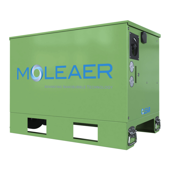
Summary of Contents for MOLEAER CLEAR
- Page 1 CLEAR INSTALLATION AND STARTUP GUIDE REV. B REFER TO OPERATING MANUAL FOR IMPORTANT SAFETY INFORMATION...
- Page 2 PAGE INTENTIONALLY LEFT BLANK...
-
Page 3: Table Of Contents
PARTS AND ACCESSORIES ...................... 3 INSTALLATION GUIDELINES ..................... 4 Installation Parts and Materials ....................4 Pipe Assembly .......................... 4 Clear Installation ........................4 Suction Piping and Intake Structure Installation ................ 6 Discharge Piping Installation ....................7 QUICK STARTUP GUIDELINES....................7 Power Input Instructions ...................... - Page 4 PAGE INTENTIONALLY LEFT BLANK Rev. B...
-
Page 5: General Information
Carefully select the Clear installation location based on the requirements specified in this section. Locate the Clear as close to the waterbody as possible in a 5 ft x 5 ft (1.5 m x 1.5 m) open area of level ground. Use the guidelines shown in Figures 1 and 2 to locate the intake structure. - Page 6 Tables 1, 2, and 3, respectively. Tables are divided by pump type, if applicable. Failure to install the Clear within the limits specified in Tables 1, 2 and 3 may void the system warranty and result in poor nanobubble production and pump cavitation.
-
Page 7: Parts And Accessories
All parts necessary to assemble up to 40 linear feet (12 linear meters), each, of suction and discharge piping are provided with purchase of a Clear Installation Kit. The actual length of pipe required will vary by installation. Additional pipe lengths may be purchased with the Clear in 10-foot (3-meter) increments. -
Page 8: Installation Guidelines
The installation diagrams for the Clear are shown in Figures 3 and 4. Using a shovel, dig a hole approximately 5 ft (1.5 m) Long (L) x 5 ft (1.5 m) Wide (W) x 1 ft (0.3 m) Deep (D). The Clear will be installed with the pressure gauges facing away from the waterbody. - Page 9 Refer to the pipe connections extending from the base of the Clear that are shown in Figure 3. Using PVC primer and cement, glue elbows to the first straight, horizontal pipe segments of suction and discharge piping and lay these pipe segments in the pipe trench with the elbows facing up.
-
Page 10: Suction Piping And Intake Structure Installation
Figures 1, 2, and 6, and in the Appendix. Use available fittings as necessary to route the suction piping from the Clear to the waterbody. Do not remove the bell end of the PVC pipe. The bell end can be used as a coupling for connecting straight pipe segments. -
Page 11: Discharge Piping Installation
Locate and install the discharge pipe following the recommendations detailed in Figures 1 and 2. Use available fittings as necessary to route the discharge piping from the Clear to the waterbody. Do not remove the bell end of the PVC pipe. The bell end can be used as a coupling for connecting straight pipe segments. -
Page 12: Power Input Instructions
Clear into the dedicated, weather- resistant power receptacle. Pump Priming Instructions Step 1. Open the enclosure of the Clear by lifting the latch hasp to open the lid and double-leaf doors. Step 2. Remove the lid from the pump strainer basket by turning it counterclockwise. -
Page 13: Suction And Discharge Operation
Suction and Discharge Operation Turn the Clear on and observe the suction and discharge locations in the waterbody. The intake should not create a vortex at the surface. If a vortex is visible, the intake screen is not properly submerged. Verify that the intake screen is resting on the floor of the waterbody and extend the suction pipe as required to position the intake screen in a deeper location of the waterbody. -
Page 14: Typical Operating Parameter Ranges
0.5 – 3.5 cfh 5 – 18 cfh Gas Flow Rate (Rotameter) If the Clear is consistently operating outside of the ranges shown in Table 7, contact a Moleaer technical service representative at (424) 558-3567. - End of Section -... -
Page 15: Document Revision History
Document Revision History Description ECO No. Assignee Date Finished Initial release. 12/28/2020 Updated figures. Added Pump Operating Envelope Appendix. 1201 4/28/2021 Added Pump Types to Tables 2 and 3. Rev. B... - Page 16 PAGE INTENTIONALLY LEFT BLANK Rev. B...
-
Page 17: Appendix: Recommended Installation/Operating Envelope
How to read the graphs: Lines are equal to The y-axis is the elevation a constant NPSHa of the base of the Clear unit above the waterline. The x-axis is the length of piping If elevation and suction pipe in the suction line. Change in the... - Page 18 Clear 50 Operating Envelope - Sparus 160 Pump 18.0 50 GPM (15 ft NPSHr) 16.0 14.0 12.0 10.0 Good 15.2 30.5 45.7 61.0 76.2 91.5 106.7 Length of Suction Pipe (ft) Clear 150 Operating Envelope - Sparus 160 Pump 16.0 150 GPM (24.5 ft NPSHr)
- Page 19 Clear 50 Operating Envelope - DAB ESWIM Pump 25.0 50 GPM (10 ft NPSHr) 20.0 Good 15.0 10.0 15.2 30.5 45.7 61.0 76.2 91.5 106.7 Length of Suction Pipe (ft) Clear 150 Operating Envelope - DAB ESWIM Pump 20.0 150 GPM (19.5 ft NPSHr) 18.0...
-
Page 20: Appendix: Instructions For Solvent Welding Pvc Pipes
APPENDIX: INSTRUCTIONS FOR SOLVENT WELDING PVC PIPES Rev. B...


Need help?
Do you have a question about the CLEAR and is the answer not in the manual?
Questions and answers