Table of Contents
Advertisement
Quick Links
U0T Series Turret & Dome
User Manual
Thank you for purchasing our product. If there are any
questions, or requests, do not hesitate to contact the
dealer.
This manual applies to the models below:
Type
Type I Camera
Type II Camera
Type III Camera
Type IV Camera
This manual may contain technical mistakes or printing
errors, and the content is subject to change without
notice. The updates will be added to the new version of
this manual. We will readily improve or update the
products or procedures described in the manual.
TURBO HD
User Manual
Model
DS-2CE78U0T-IT3F
DS-2CE76U0T-ITPF
DS-2CE76U0T-ITMF
DS-2CE57U0T-VPITF
Camera
0100001090220
Advertisement
Table of Contents

Related Manuals for HIKVISION TURBO HD U0T Series


Summary of Contents for HIKVISION TURBO HD U0T Series
- Page 1 TURBO HD U0T Series Turret & Dome Camera User Manual User Manual Thank you for purchasing our product. If there are any questions, or requests, do not hesitate to contact the dealer. This manual applies to the models below: Type Model Type I Camera DS-2CE78U0T-IT3F...
- Page 2 Regulatory Information FCC Information Please take attention that changes or modification not expressly approved by the party responsible for compliance could void the user’s authority to operate the equipment. FCC compliance: This equipment has been tested and found to comply with the limits for a Class A digital device, pursuant to part 15 of the FCC Rules.
- Page 3 Safety Instruction These instructions are intended to ensure that user can use the product correctly to avoid danger or property loss. The precaution measure is divided into “Warnings” and “Cautions”. Warnings: Serious injury or death may occur if any of the warnings are neglected.
- Page 4 While in delivery, the camera shall be packed in its original packing, or packing of the same texture. Mark Description Table 0-1 Mark Description Mark Description DC Voltage 1 Introduction 1.1 Product Features The main features are as follows: High performance CMOS sensor ...
-
Page 5: Installation
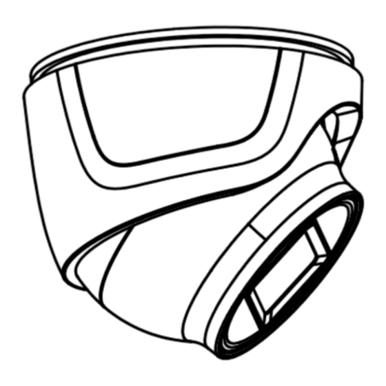
1.2.3 Overview of Type III Camera Mounting Base Clip Plate Enclosure Main Body Switch Button Power Cord DC 12 V Video Cable Figure 1-3 Overview of Type III Camera Note: Press and hold the switch button for 5 seconds to switch the video output. - Page 6 mounting as the reference, when adopting the wall mounting. Steps: 1. Disassemble the turret camera by rotating the camera to align the notch to one of the marks, as shown in the figure below. Mark Notch Figure 2-1 Disassemble the Camera 2.
- Page 7 Figure 2-4 Secure the Camera with Mounting Base 8. Connect the corresponding cables, such as power cord, and video cable. 9. Power on the camera to check whether the image on the monitor is gotten from the optimum angle. If not, adjust the camera according to the figure below to get an optimum angle.
- Page 8 Figure 2-7 Drill Template Note: Drill the cable hole in the center of the drill template, when adopting the ceiling outlet to route the cable. 5. Secure the mounting base to the ceiling with the supplied screws. Expansion Bolts Self-tapping Screws Figure 2-8 Fix the Mounting Base to the Ceiling Note:...
- Page 9 1). Hold the camera body and rotate the enclosure to adjust the pan position [0° to 360°]. 2). Move the camera body up and down to adjust the tilt position [0° to 75°]. 3). Rotate the camera body to adjust the rotation position [0°...
- Page 10 For cement wall/ceiling, expansion bolts are required to fix the camera. For wooden wall/ceiling, self-tapping screws are required. 6. Route the cables through the cable hole, or the side opening. 7. Secure the camera on the mounting base. 1) pull out the clip plate, and then to combine the camera with the mounting base.
- Page 11 Note: Cable hole is required, when adopting the ceiling outlet to route cables. 3. Loosen the screws to remove the bubble. Figure 2-17 Remove the Bubble Note: You do not have to loosen those screws entirely. Remove the bubble with care. The bubble is ...
- Page 12 Figure 2-20 Bubble Reinstallation...
-
Page 13: Menu Description
3 Menu Description Follow the steps below to call the menu. Note: The actual display may vary with your camera model. Steps: 1. Connect the camera with the DVR, and the monitor, shown as the figure 3-1. Figure 3-1 Connection 2. -
Page 14: Video Format
3.1 VIDEO FORMAT You can set the video format to 8MP@12.5 fps, 8 MP@15fps, 4MP@25fps, 4MP@30fps, 2MP@25fps, and 2MP@30fps. 3.2 EXPOSURE Exposure describes the brightness-related parameters, which can be adjusted by EXPOSURE MODE, and AGC. Figure 3-3 EXPOSURE EXPOSURE MODE You can set the EXPOSURE MODE to GLOBAL, BLC, HLC, and DWDR. -
Page 15: Video Settings
Figure 3-4 B&W IR LIGHT You can turn on/off the IR LIGHT to meet the requirements of different circumstances. SMART IR The Smart IR function is used to adjust the light to its most suitable intensity, and prevent the image from over exposure. -
Page 16: Image Mode
BRIGHTNESS, CONTRAST, SHARPNESS, SARUTATION, and DNR are adjustable. VIDEO SETTINGS IMAGE MODE WHITE BALANCE BRIGHTNESS CONTRAST SHARPNESS SATURATION BACK EXIT SAVE & EXIT Figure 3-6 VIDEO SETTINGS IMAGE MODE IMAGE MODE is used to adjust the image saturation, and you can set it to STD (Standard), or HIGH-SAT (High Saturation). -
Page 17: Factory Default
much it is distributed across the spectrum of different wavelengths. DNR (Digital Noise Reduction) The DNR function can decrease the noise effect, especially when capturing moving images in poor light conditions and delivering more accurate and sharp image. 3.5 FACTORY DEFAULT Move the cursor to FACTORY DEFAULT and click Iris+ to reset all the settings to the factory default.
Need help?
Do you have a question about the TURBO HD U0T Series and is the answer not in the manual?
Questions and answers