Advertisement
NIS6432/52 Evaluation
Board User's Manual
EVBUM2768/D
Instructions
•
Remove all jumpers from the headers if there are any present
•
Connect voltage probes to Vin, Vout, and Enable/Fault
•
There is a potentiometer to adjust the current limit set resistor from
5 kW to 55 kW. If testing outside this range is needed, remove and
replace the R
resistor with one of a different value
limMIN
•
Connect 3.3 or 5 V to V
CC
•
The output may be connected to a load
•
Normally the board will have two green LEDs on. The one on the left
is for the enable/fault pin and the one on the right is for the output
voltage
•
Grounding EN, connecting SAS to +3.3 or +5 V, or connecting
a voltage to the external MOSFET M2 via the GATE test point will
turn the eFuse off. When the eFuse is off both green lights will turn
off and the yellow LED will turn on to indicate that the enable/fault
pin is low
•
Input and output capacitors and Zeners are provided for testing
purposes but are generally not needed for proper function of the
NIS6432 and NIS6452 devices
© Semiconductor Components Industries, LLC, 2020
October, 2020 − Rev. 0
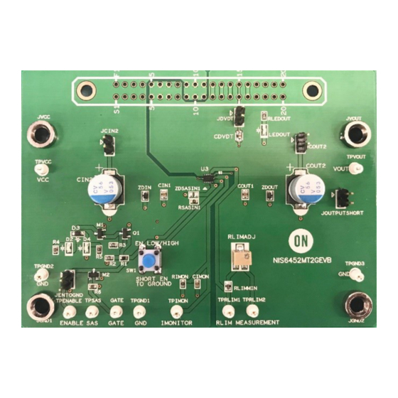
Figure 2. Features of the Evaluation Board
1
www.onsemi.com
EVAL BOARD USER'S MANUAL
Figure 1. The Evaluation Board
Publication Order Number:
EVBUM2768/D
Advertisement
Table of Contents

Subscribe to Our Youtube Channel
Related Manuals for ON Semiconductor NIS6432


Summary of Contents for ON Semiconductor NIS6432
- Page 1 Input and output capacitors and Zeners are provided for testing Figure 1. The Evaluation Board purposes but are generally not needed for proper function of the NIS6432 and NIS6452 devices Figure 2. Features of the Evaluation Board Publication Order Number: ©...
- Page 2 Figure 3. The eFuse Turning On with the EN Pin Initially Grounded and then Allowed to Float. Do Not Force a Voltage on the EN Pin on the NIS6432/52 Figure 4. The eFuse Operating Normally and then Turning Off as the EN Pin is Pulled to Ground...
- Page 3 EVBUM2768/D Figure 5. The Input Voltage is Ramped High and then Back Down again to Show the Overvoltage Clamping Feature Figure 6. The Input Voltage is Brought Low and then Back High to Show the Undervoltage Lockout Feature www.onsemi.com...
- Page 4 EVBUM2768/D Figure 7. The eFuse with the Output Shorted to Ground Auto−retrying with a Low R Figure 8. The eFuse with the Output Shorted to Ground Auto−retrying with a High R www.onsemi.com...
- Page 5 EVBUM2768/D SCHEMATIC Figure 9. The NIS6432/52 Evaluation Board Schematic www.onsemi.com...
-
Page 6: Bill Of Materials
E−Switch TL1105FF160Q NIS6432MT1/ − ON Semiconductor − NIS6432MT2/ NIS6452MT1/ NIS6452MT2 ZDIN, ZDOUT 16 Vz MM3Z16VT1GOSCT−ND ON Semiconductor MM3Z16VT1G Cathode toward top of ZDSASIN − ON Semiconductor Do not − − populate − CON40 S3314−ND Sullins EBC20DRTH Do not populate www.onsemi.com... -
Page 7: Additional Information
onsemi, , and other names, marks, and brands are registered and/or common law trademarks of Semiconductor Components Industries, LLC dba “onsemi” or its affiliates and/or subsidiaries in the United States and/or other countries. onsemi owns the rights to a number of patents, trademarks, copyrights, trade secrets, and other intellectual property. A listing of onsemi’s product/patent coverage may be accessed at www.onsemi.com/site/pdf/Patent−Marking.pdf.
Need help?
Do you have a question about the NIS6432 and is the answer not in the manual?
Questions and answers