Table of Contents
Advertisement
Quick Links
Advertisement
Table of Contents

Subscribe to Our Youtube Channel
Related Manuals for Komfovent RHP Pro2


Summary of Contents for Komfovent RHP Pro2
- Page 1 RHP Pro2 INSTALLATION MANUAL...
-
Page 2: Table Of Contents
6.1. Control panel C5.1 ......................................45 6.2. Starting the Unit With a Computer ................................47 6.3. Calibration of Clean Filters ..................................... 50 6.4. Quick Inspection ........................................ 51 UAB KOMFOVENT we reserve the right to make changes without prior notice RHP Pro2_installation manual_23-05... -
Page 3: Introduction
1. INTRODUCTION This Installation Manual is intended for professionals, qualified to install RHP Pro2 air handling units. Qualified profes- sionals are people with sufficient professional experience and knowledge of ventilation systems and installation thereof, knowledge of electrical safety requirements and having ability to perform works without endangering themselves or others. -
Page 4: Unit Types And Sizes
RHP Pro2 – air handling units with a rotary heat exchanger and an integrated heat pump. Rotating wheel (rotor) of a rotary heat exchanger collects heat or cold from the indoor air and transfers it to the fresh supply air. Recovered heat/cold capacity is changed by adjusting the rotor speed. -
Page 5: Unit Components And Sections
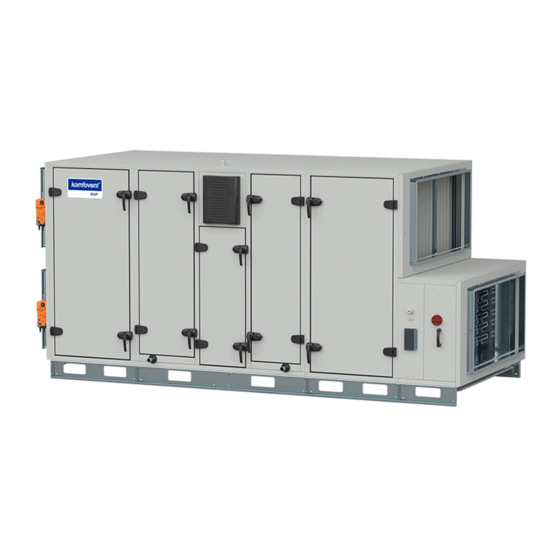
1.3. Unit Components and Sections RHP Pro2 air handling units are assembled from separate sections. Depending on the order and unit size, sections may be pre-assembled in a factory or transported separately. Type of each section is marked with a label attached to the section door. -
Page 6: Heat Pump Section
5 – condensate drainage pipes, 6 – heat pump assembly, 7 – rotor motor, 8 – frequency inverter for heat pump compressor, 9 – rotary recuperator marking label, 10 – heat pump section label UAB KOMFOVENT we reserve the right to make changes without prior notice RHP Pro2_installation manual_23-05... - Page 7 1 – rotor wheel, 2 – automation box, 3 – automatic switch, 4 – rotor wheel brush seals, 5 – rotor belt, 6 – rotor gear motor, 7 – rotor section label UAB KOMFOVENT we reserve the right to make changes without prior notice RHP Pro2_installation manual_23-05...
- Page 8 13 – Sight glass, 14 – Electronic expansion valve (EXV), 15 – High pressure transmiter (HPT), 16 – High pressure pressostat (HP), 17 – condensate trays, 18 – condensate drainage pipes, 19 – drop eliminator UAB KOMFOVENT we reserve the right to make changes without prior notice RHP Pro2_installation manual_23-05...
- Page 9 This results in reduced operating life and increased probability of failure. Depends on configuration. UAB KOMFOVENT we reserve the right to make changes without prior notice RHP Pro2_installation manual_23-05...
-
Page 10: Recirculation Section
Recirculation section is intended for mixing extract and supply air for heating or cooling thereof by reducing energy consumption of heaters/coolers. Fig. 6. Recirculation section 1 – air mixing damper, 2 – damper actuator, 3 – recirculation section label UAB KOMFOVENT we reserve the right to make changes without prior notice RHP Pro2_installation manual_23-05... -
Page 11: Cooler And Heater Sections
(see Chapter “Requirements for Electrical Connection”). A water heater is fitted with a return water temperature sensor, which protects the heat exchanger against freezing. Sensor installation procedure is described in Chapter “Installation of External Heating/Cooling Devices”. UAB KOMFOVENT we reserve the right to make changes without prior notice RHP Pro2_installation manual_23-05... -
Page 12: Air Dampers
Fig. 9. Air closing dampers 1 – air damper, 2 – electric damper actuator UAB KOMFOVENT we reserve the right to make changes without prior notice RHP Pro2_installation manual_23-05... -
Page 13: Silencers
1.3.7. Humidifier section RHP Pro2 units that was ordered with humidity function can control external steam humidifier. Humidifier generates steam that reaches steam distributors located inside of the AHU in the supply airflow. A drop eliminator is placed inside the humidifier section to prevent excess condensate from entering the ducts, so an additional drainage pipe must be connected to this section (see section “Connection of a condensate drain”). -
Page 14: Smoke Extraction Section
In smoke extraction mode, fan assembly and control electronics will maintain its operational and mechanical stability for at least 60 min. at 70°C of extracted air/smoke temperature. UAB KOMFOVENT we reserve the right to make changes without prior notice RHP Pro2_installation manual_23-05... -
Page 15: Inspection Sides
1.4. Inspection Sides Depending on the installation position and connection of air ducts, RHP Pro2 air handling units are available in four in- spection sides. Inspection side is determined by a supply air duct (SUP) position: L1 Air duct for supply air connected on the left bottom side of the unit... -
Page 16: Unit Transportation And Storage
Max. 60° Max. 60° Fig. 14. Lifting of individual sections Lifting means (pipes, belts, ropes, traverses) are not included. UAB KOMFOVENT we reserve the right to make changes without prior notice RHP Pro2_installation manual_23-05... - Page 17 A - A >L Max. 60° Fig. 15. Lifting AHU fully assembled onto reinforced mounting frame Lifting means (pipes, belts, ropes, traverses) are not included. UAB KOMFOVENT we reserve the right to make changes without prior notice RHP Pro2_installation manual_23-05...
- Page 18 (dust, rain, cold, etc.). UAB KOMFOVENT we reserve the right to make changes without prior notice RHP Pro2_installation manual_23-05...
-
Page 19: Mechanical Installation
3.1. Requirements for Mounting Location and Installation Base RHP Pro2 air handling units are designed for ventilation of medium or large commercial or industrial premises (e.g., stores, offices, hotels, etc.) where standard air temperature and humidity is maintained. These units are not intended for transporting solid particles within air flows. -
Page 20: Inspection Area
Unit size 1110 1260 1410 1610 1810 2010 2210 Measurements in the table are approximate. For exact unit measurements see the technical data print-out. UAB KOMFOVENT we reserve the right to make changes without prior notice RHP Pro2_installation manual_23-05... -
Page 21: Door Handles And Hinges
3.3. Door Handles and Hinges RHP Pro2 door handles are designed in such a way that the unit door does not swing open due to the pressure accumu- lated inside the unit and does not injure the person opening the door. By pressing the handle, the door slightly opens and locks to release air pressure inside the unit. -
Page 22: Connection Of Sections
2–3 mm. If the unit is ordered with an installation frame, additionaly sections shall be tightened through the designated holes in the installation frame (insert internal section connection screws first, before tightening installation frame). UAB KOMFOVENT we reserve the right to make changes without prior notice RHP Pro2_installation manual_23-05... - Page 23 1 – fan section tightening angle-piece, 2 – wall to which the fan is mounted, 3 – other section tightening angle-piece, 4 – grommet d29 UAB KOMFOVENT we reserve the right to make changes without prior notice RHP Pro2_installation manual_23-05...
-
Page 24: Installation Of External Heating/Cooling Devices
3.5. Installation of External Heating/Cooling Devices Based on their equipment, RHP Pro2 air handling units may be operated with various heating or cooling devices. Heaters/ coolers are usually installed in separate sections that are connected at the end of the unit (in the supply air stream). For air handling units with R1 or L1 inspection sides, heater/cooler sections are mounted on an installation frame and connected at the bottom part of the unit. - Page 25 Fig. 26. Installation of a surface-mounted return water temperature sensor Depending on the order. Depending on the order. UAB KOMFOVENT we reserve the right to make changes without prior notice RHP Pro2_installation manual_23-05...
- Page 26 PPU must be installed as close to the water coil as possible. Depending on the order. It is recommended to use PPU made by Komfovent. UAB KOMFOVENT we reserve the right to make changes without prior notice RHP Pro2_installation manual_23-05...
-
Page 27: Connection Of A Condensate Drain
Condensate collection location must be easily accessible for cleaning and disinfection. Fig. 30. Condensate drain connection to sewer system UAB KOMFOVENT we reserve the right to make changes without prior notice RHP Pro2_installation manual_23-05... -
Page 28: Connection To Air Ducts
(ducts, flexible connectors, duct heaters/coolers, silencers and etc.) directly to the air damper, they should also have an L-20 flange connection for easier installation. UAB KOMFOVENT we reserve the right to make changes without prior notice RHP Pro2_installation manual_23-05... -
Page 29: Outdoor Units
3.8. Outdoor Units RHP Pro2 air handling units for outdoor installation must be additionally protected against environmental effects by installing a protective roof and exhaust air hoods. Units shall be mounted on an installation frame which is attached to an installation base. - Page 30 RHP PRO2 12-72 b+120 d+120 a+120 UAB KOMFOVENT we reserve the right to make changes without prior notice RHP Pro2_installation manual_23-05...
- Page 31 Fig. 34. Installation of a separately ordered protective roof Part count and measurements may differ depending on the unit type or project requirements. UAB KOMFOVENT we reserve the right to make changes without prior notice RHP Pro2_installation manual_23-05...
-
Page 32: Electrical Installation
Air handling units designed for 400 VAC, 50 Hz supply voltage, connected through the main circuit breaker (QS1 in wiring diagrams). The main circuit breaker comes with a universal bracket that allows fixing it on the top or side of the AHU. UAB KOMFOVENT we reserve the right to make changes without prior notice RHP Pro2_installation manual_23-05... - Page 33 If circuit breaker bracket is used, it must be mounted on the edge of the unit casing, otherwise self- tapping screws may damage wires or tubing that is routed inside. UAB KOMFOVENT we reserve the right to make changes without prior notice RHP Pro2_installation manual_23-05...
- Page 34 4 – automatic switch, 5 – electronic heater control board Large RHP Pro2 units (size 62 and larger) also has a separate power circuit breaker for the heat pump section. Lead-in cable diameter depends on a maximum current specified in the technical data print-out of the specific unit.
-
Page 35: Connection Of Electrical Components
Fig. 38. Main board of the C5 control panel 1 – control panel connection, 2 – Intranet or Internet connection, 3 – inner connections of components, 4 – terminals for external components UAB KOMFOVENT we reserve the right to make changes without prior notice RHP Pro2_installation manual_23-05... - Page 36 B5 (9–10) – when a water heater is installed, this terminal is used for connecting a return water temperature sensor (NTC 10kΩ) which protects against freezing. UAB KOMFOVENT we reserve the right to make changes without prior notice RHP Pro2_installation manual_23-05...
- Page 37 >2D Fig. 43. Installation of a supply air temperature sensor Depending on the order. Depending on the order. UAB KOMFOVENT we reserve the right to make changes without prior notice RHP Pro2_installation manual_23-05...
- Page 38 If the DX device was not predefined in the controller software, these outputs will be inactive. UAB KOMFOVENT we reserve the right to make changes without prior notice RHP Pro2_installation manual_23-05...
- Page 39 Grommets are fastened to ensure tightness. Depending on whether the wires will be pulled up or down, break a tab at the top or bottom edge of the box cover. Fig. 45. Automation box cover UAB KOMFOVENT we reserve the right to make changes without prior notice RHP Pro2_installation manual_23-05...
-
Page 40: Control Panel Installation
Fig. 47. Control panel cable wiring Do not use sharp tools for pinning contacts in the control panel (e.g., screwdriver). Please use a pencil or a ballpoint pen. UAB KOMFOVENT we reserve the right to make changes without prior notice RHP Pro2_installation manual_23-05... -
Page 41: Connection Of Cables And Wires Between Sections
(fans, valves, rotor wheel). If nec- essary, use special ties to attach the wires to the unit housing. UAB KOMFOVENT we reserve the right to make changes without prior notice RHP Pro2_installation manual_23-05... -
Page 42: Connecting The Unit To The Internal Computer Network Or The Internet
An air handling unit connected to a network router can be controlled by a computer via wireless connection (Wi-Fi). The unit may also be controlled wirelessly in a local network using a smart phone with the Komfovent app. Once the unit is con- nected to the network router, you should assign a free IP address on the local network. - Page 43 IP address. Depending on whether you will use your computer or smart phone with the Komfovent app to control your AHU, you will also need to enter a corresponding port number to the router.
-
Page 44: Filters
5. FILTERS Air filters are intended for removing dust, bacteria and other fine particles from the supplied and extracted air. RHP Pro2 air handling units are fitted with bag filters, since they have a larger filtering surface than compact filters and will require less frequent filter replacement. -
Page 45: Commissioning And Inspection Of The Unit
16:30 21,9 °C 21,3 °C Temperature ECONOMY 1 Fig. 54. Control panel Sold separately. UAB KOMFOVENT we reserve the right to make changes without prior notice RHP Pro2_installation manual_23-05... - Page 46 21,3 °C Temperature STARTING To change the ventilation mode settings: select a desired mode and set a desired air volume or temperature with the arrows. UAB KOMFOVENT we reserve the right to make changes without prior notice RHP Pro2_installation manual_23-05...
-
Page 47: Starting The Unit With A Computer
Login to the C5 control panel interface in a window that opens: enter the user name user, password user and press CONNECT. If the password was changed, use the changed password. UAB KOMFOVENT we reserve the right to make changes without prior notice RHP Pro2_installation manual_23-05... - Page 48 10.0 °C 27.9 °C 30 % Settings 2000 m³/h 26 °C 2000 m³/h 100% AHU control ĮOn/Off Operation mode Economy1 Active functions Alarm status No alarms UAB KOMFOVENT we reserve the right to make changes without prior notice RHP Pro2_installation manual_23-05...
- Page 49 2. Select a desired ventilation mode from the list. 3. Enter desired air flow and temperature in the selected mode settings. 4. Press “Save” button at the bottom of the screen. UAB KOMFOVENT we reserve the right to make changes without prior notice RHP Pro2_installation manual_23-05...
-
Page 50: Calibration Of Clean Filters
You can stop the unit by pressing ON/OFF button in the “Overview” window. 6.3. Calibration of Clean Filters RHP Pro2 control automation continuously monitors filter contamination. Pressure drop of clean filters is preset in the factory. If filters are from another manufacturer or of different filtering class, we recommend performing initial calibration of clean filters before commissioning of the unit. -
Page 51: Quick Inspection
The heat pump compressor operates properly, without any extraneous noise and vibrations. HP heat exchanger calibration performed (only in HP units) Other comments: Installer Company Tel. No. Date Signature UAB KOMFOVENT we reserve the right to make changes without prior notice RHP Pro2_installation manual_23-05... - Page 52 SERVICE AND SUPPORT PARTNERS LITHUANIA J. PICHLER Gesellschaft m. b. H. www.pichlerluft.at UAB KOMFOVENT Phone: +370 5 200 8000 Ventilair group www.ventilairgroup.com ACB Airconditioning www.acbairco.be service@komfovent.com www.komfovent.com REKUVENT s.r.o. www.rekuvent.cz SWEDEN Komfovent AB WESCO AG www.wesco.ch Ögärdesvägen 12A SUDCLIMATAIR SA www.sudclimatair.ch...
Need help?
Do you have a question about the RHP Pro2 and is the answer not in the manual?
Questions and answers