Komfovent VERSO STANDARD Installation Manual
Hide thumbs
Also See for VERSO STANDARD:
- Installation manual (48 pages) ,
- User manual (48 pages) ,
- Installation and maintenance service manual (32 pages)
Table of Contents
Advertisement
Advertisement
Table of Contents

Related Manuals for Komfovent VERSO STANDARD


Summary of Contents for Komfovent VERSO STANDARD
- Page 1 VERSO STANDARD INSTALLATION MANUAL...
-
Page 3: Table Of Contents
8. COMMISSIONING AND INSPECTION OF THE UNIT ....................62 8.1. Control panel C5.1 .................................62 8.2. Starting the Unit With a Computer ..........................65 8.3. Quick Inspection ..................................67 UAB KOMFOVENT we reserve the right to make changes without prior notice Verso Standard_ installation manual_24-03... -
Page 4: Introduction
1. INTRODUCTION This Installation Manual is intended for professionals, qualified to install Verso Standard air handling units. Qualified professionals are people with sufficient professional experience and knowledge of venti- lation systems and installation thereof, knowledge of electrical safety requirements and having ability to perform works without endangering themselves or others. -
Page 5: Unit Types And Sizes
/h). 1.2.1. Unit types by heat recovery type All Verso Standard air handling units are divided into 3 groups according to the type of recuperator (heat exchanger) used: Verso R - air handling units with rotary heat exchangers. Rotating wheel (rotor) of a rotary heat ex- changer collects heat or cold from the indoor air and transfers it to the fresh supply air. -
Page 6: Unit Types By Duct Connections
• Horizontal unit Vertical unit Flat unit Fig. 1. Classification of units by duct connection UAB KOMFOVENT we reserve the right to make changes without prior notice Verso Standard_ installation manual_24-03... -
Page 7: Unit Types By Inspection Sides
Left inspection side Air duct to the premises Air duct to the premises Fig. 3. Classification of units by inspection side Depends on your order. UAB KOMFOVENT we reserve the right to make changes without prior notice Verso Standard_ installation manual_24-03... -
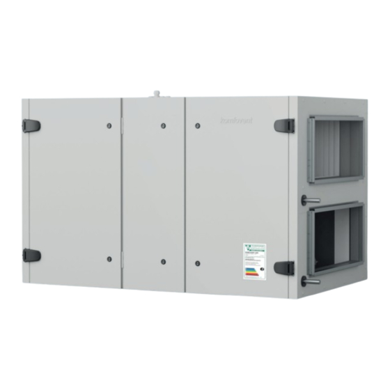
Page 8: Unit Components
Left inspection side L1 7 12 Verso R 2500 H Right Inspection side R1 Left inspection side L1 Right Inspection side R2 Left inspection side L2 UAB KOMFOVENT we reserve the right to make changes without prior notice Verso Standard_ installation manual_24-03... - Page 9 12 4 12 4 Verso R 5000 H Right Inspection side R1 Left inspection side L1 Right Inspection side R2 Left inspection side L2 UAB KOMFOVENT we reserve the right to make changes without prior notice Verso Standard_ installation manual_24-03...
- Page 10 Right Inspection side R1 Left inspection side L1 2 11 Verso CF 2300 UH Right Inspection side R1 Left inspection side L1 2 11 UAB KOMFOVENT we reserve the right to make changes without prior notice Verso Standard_ installation manual_24-03...
- Page 11 9 – air bypass valve 10 – rotary heat exchanger – exhaust air 11 – C5 controller main board 12 – Lead-in wire * Depending on the order. UAB KOMFOVENT we reserve the right to make changes without prior notice Verso Standard_ installation manual_24-03...
-
Page 12: Vertical Units
9 – air bypass valve 10 – rotary heat exchanger – exhaust air 11 – C5 controller main board 12 – Lead-in wire * Depending on the order. UAB KOMFOVENT we reserve the right to make changes without prior notice Verso Standard_ installation manual_24-03... - Page 13 9 – air bypass valve 10 – rotary heat exchanger – exhaust air 11 – C5 controller main board 12 – Lead-in wire * Depending on the order. UAB KOMFOVENT we reserve the right to make changes without prior notice Verso Standard_ installation manual_24-03...
- Page 14 9 – air bypass valve 10 – rotary heat exchanger – exhaust air 11 – C5 controller main board 12 – Lead-in wire * Depending on the order. UAB KOMFOVENT we reserve the right to make changes without prior notice Verso Standard_ installation manual_24-03...
- Page 15 9 – air bypass valve 10 – rotary heat exchanger – exhaust air 11 – C5 controller main board 12 – Lead-in wire * Depending on the order. UAB KOMFOVENT we reserve the right to make changes without prior notice Verso Standard_ installation manual_24-03...
- Page 16 9 – air bypass valve 10 – rotary heat exchanger – exhaust air 11 – C5 controller main board 12 – Lead-in wire * Depending on the order. UAB KOMFOVENT we reserve the right to make changes without prior notice Verso Standard_ installation manual_24-03...
- Page 17 9 – air bypass valve 10 – rotary heat exchanger – exhaust air 11 – C5 controller main board 12 – Lead-in wire * Depending on the order. UAB KOMFOVENT we reserve the right to make changes without prior notice Verso Standard_ installation manual_24-03...
- Page 18 Verso CF 1000 UV - 1300 UV - 1700 UV Right Inspection side R1 Left inspection side L1 Verso CF 2300 UV Right Inspection side R1 Left inspection side L1 2 11 UAB KOMFOVENT we reserve the right to make changes without prior notice Verso Standard_ installation manual_24-03...
- Page 19 9 – air bypass valve 10 – rotary heat exchanger – exhaust air 11 – C5 controller main board 12 – Lead-in wire * Depending on the order. UAB KOMFOVENT we reserve the right to make changes without prior notice Verso Standard_ installation manual_24-03...
- Page 20 9 – air bypass valve 10 – rotary heat exchanger – exhaust air 11 – C5 controller main board 12 – Lead-in wire * Depending on the order. UAB KOMFOVENT we reserve the right to make changes without prior notice Verso Standard_ installation manual_24-03...
-
Page 21: Flat Units
UAB KOMFOVENT we reserve the right to make changes without prior notice Verso Standard_ installation manual_24-03... - Page 22 Left inspection side L2/R1 12 11 Verso CF 1000 F - 1300 F - 1500 F Right Inspection side R2/L1 Left inspection side L2/R1 11 12 3 UAB KOMFOVENT we reserve the right to make changes without prior notice Verso Standard_ installation manual_24-03...
- Page 23 10 – rotary heat exchanger 11 – C5 controller main board – exhaust air 12 – Lead-in wire 13 – Noise suppressor section * Depending on the order. UAB KOMFOVENT we reserve the right to make changes without prior notice Verso Standard_ installation manual_24-03...
-
Page 24: Unit Transportation And Storage
Max. 0,3 m ≥L Fig. 5. Examples of transportation by crane, forklift and trolley UAB KOMFOVENT we reserve the right to make changes without prior notice Verso Standard_ installation manual_24-03... - Page 25 (e.g., wet cardboard packaging), notify the carrier immediately. If the damage is significant, do not accept the unit. Inform the selling company or the representative of UAB KOMFOVENT within three business days about any damage detected during delivery.
-
Page 26: Mechanical Installation
3. MECHANICAL INSTALLATION 3.1. Requirements for Mounting Location and Installation Base Verso Standard air handling units are designed for ventilation of medium or large commercial or indus- trial premises (e.g., stores, offices, hotels, etc.) where standard air temperature and humidity is maintained. - Page 27 Verso CF flat units with counterflow heat exchanger must be hung with a slope 15–20 mm on the drainage side to facilitate the discharge of condensate from the unit. UAB KOMFOVENT we reserve the right to make changes without prior notice Verso Standard_ installation manual_24-03...
- Page 28 16,5 49,5 13,5 43,5 Verso CF 1500 F 1133 16,5 49,5 13,5 43,5 Verso CF 2000 F 1634 Verso CF 2500 F 2034 52,5 UAB KOMFOVENT we reserve the right to make changes without prior notice Verso Standard_ installation manual_24-03...
- Page 29 1086 1179 772,5 772,5 Verso R 1000 FSA 1086 Verso R 1500 F UAB KOMFOVENT we reserve the right to make changes without prior notice Verso Standard_ installation manual_24-03...
-
Page 30: Inspection Area
For repair and replacement of components (e.g., removal of rotary heat exchangers), access area equal or wider to the width of the device B shall be ensured in front of the device. UAB KOMFOVENT we reserve the right to make changes without prior notice Verso Standard_ installation manual_24-03... - Page 31 UAB KOMFOVENT we reserve the right to make changes without prior notice Verso Standard_ installation manual_24-03...
-
Page 32: Connection Of Sections
C – with a mounting frame that should be ordered separately Connect connecting cables and wires of the sections (see Chapter “Electrical Installation”) before fas- tening sections of an air handling unit. UAB KOMFOVENT we reserve the right to make changes without prior notice Verso Standard_ installation manual_24-03... - Page 33 1 – edge of the first section to be tightened, 2 – edge of the second section to be tightened, 3 – screw M8, 4 – washer, 5 – threaded bushing, 6 – adhesive gasket, 7 – gasket on a shelf separating different air flows, 8 – external tightening elements UAB KOMFOVENT we reserve the right to make changes without prior notice Verso Standard_ installation manual_24-03...
- Page 34 3. Adhesive gasket 4. Screw M8 5. Washer 6. Supply air temperature sensor connection Fig. 11. Verso R 1000 FSA connection and sealing of unit sections UAB KOMFOVENT we reserve the right to make changes without prior notice Verso Standard_ installation manual_24-03...
-
Page 35: Duct System Installation
It is recommended to insulate the ducts in unheated rooms (attic, basement) to avoid heat loss. It is also recommended to insulate the supply air ducts if the unit is used for room cooling. UAB KOMFOVENT we reserve the right to make changes without prior notice Verso Standard_ installation manual_24-03... - Page 36 Duct system elements must have separate brackets and to be mounted in a way that their weight is not shifted to the unit casing. UAB KOMFOVENT we reserve the right to make changes without prior notice Verso Standard_ installation manual_24-03...
- Page 37 350 × 1100 350 × 1100 350 × 1100 5000 H Rectangular 1100 × 400 1100 × 400 1100 × 400 1100 × 400 UAB KOMFOVENT we reserve the right to make changes without prior notice Verso Standard_ installation manual_24-03...
-
Page 38: Installation Of External Heating/Cooling Devices
The sensor must be thermally insulated so that the room temperature does not distort water temperature measurements. Fig. 13. Installation of a return water temperature sensor UAB KOMFOVENT we reserve the right to make changes without prior notice Verso Standard_ installation manual_24-03... -
Page 39: Connection Of A Condensate Drain
H mm p > 0 H mm H/2 mm Fig. 14. Installation of a siphon It is recommended to use PPU made by Komfovent. UAB KOMFOVENT we reserve the right to make changes without prior notice Verso Standard_ installation manual_24-03... - Page 40 Condensate collection location must be easily accessible for cleaning and disinfection. Fig. 16. Condensate drain connection to sewer system UAB KOMFOVENT we reserve the right to make changes without prior notice Verso Standard_ installation manual_24-03...
-
Page 41: Outdoor Units
3.7. Outdoor Units Verso Standard air handling units are not suitable to install in outdoor areas without additional modification. Units intended be installed outdoor, should be fixed to the base frame and air dampers must be in- stalled on to the duct connections. AHU must be protected from the weather influence by installing dedi- cated roof and hoods. -
Page 42: Technical Information
2 × 1850 5000 H 3~400 29,7 3~400 2 × 2263 Parameters of hot water 60–40°C. Water duct air heater (DH). It should be ordered. UAB KOMFOVENT we reserve the right to make changes without prior notice Verso Standard_ installation manual_24-03... -
Page 43: Unit Dimensions
340 340 340 340 (751, 370, 751) 1872 Left L2 1300 1300 340 340 340 340 (751, 370, 751) (L1,L2) – when the device from the sections. UAB KOMFOVENT we reserve the right to make changes without prior notice Verso Standard_ installation manual_24-03... - Page 44 5000 H 2327 Left L1 1410 1250 327,5 322,5 327,5 322,5 150 680 680 680 680 (504,1319,504) (L1,L2) – when the device from the sections. UAB KOMFOVENT we reserve the right to make changes without prior notice Verso Standard_ installation manual_24-03...
-
Page 45: Vertical Units
Left L1 1400 1391/1340 286 785 286 785 150 698 698 698 698 (500, 1315, 500) (L1,L2) – when the device from the sections. UAB KOMFOVENT we reserve the right to make changes without prior notice Verso Standard_ installation manual_24-03... -
Page 46: Flat Units
1500 F Right R1 1645/1600 1810/1750 2000 F Left L1 1645/1600 1810/1750 Right R2/L1 2045/2000 1910/1850 263,5 2500 F Left L2/R1 2045/2000 1910/1850 263,5 UAB KOMFOVENT we reserve the right to make changes without prior notice Verso Standard_ installation manual_24-03... -
Page 47: Electrical Installation
Inspect the power cable ant other wiring for damage in insulation. • Locate the wiring diagram for your unit according to the unit type. UAB KOMFOVENT we reserve the right to make changes without prior notice Verso Standard_ installation manual_24-03... -
Page 48: Requirements For Electrical Connection
5 × 4,0 mm (Cu) 5 × 6,0 mm (Cu) 5 × 10,0 mm (Cu) 5 × 16,0 mm (Cu) 5 × 25,0 mm (Cu) UAB KOMFOVENT we reserve the right to make changes without prior notice Verso Standard_ installation manual_24-03... -
Page 49: Connection Of Electrical Components
Fig. 18. C5 controller main board 1 – control panel connection, 2 – Intranet or Internet connection, 3 – inner connections of components, 4 – terminals for external components UAB KOMFOVENT we reserve the right to make changes without prior notice Verso Standard_ installation manual_24-03... - Page 50 Modbus RTU protocol. Also these terminals can be used for additional heating/cooling zone control module connection (see „Additional zone control installation manual“). UAB KOMFOVENT we reserve the right to make changes without prior notice Verso Standard_ installation manual_24-03...
- Page 51 Fig. 20. Return water temperature sensor B1 (11–12) – terminal for a supply air temperature sensor (NTC 10kΩ) for controlling air temperature. Fig. 21. Supply air temperature sensor UAB KOMFOVENT we reserve the right to make changes without prior notice Verso Standard_ installation manual_24-03...
- Page 52 FG1 (37–39) – terminals used to connect air damper actuators. These terminals may also be used for connecting 24 V AC power supply actuators with or without a spring return. UAB KOMFOVENT we reserve the right to make changes without prior notice Verso Standard_ installation manual_24-03...
-
Page 53: Control Panel Installation
Control panel is supplied with a 10 m cable. If this cable is too short, you can replace it with a 4 × 0.22 mm cable, up to 150 m long. If the DX device was not predefined in the controller software, these outputs will be inactive. UAB KOMFOVENT we reserve the right to make changes without prior notice Verso Standard_ installation manual_24-03... - Page 54 Fig. 24. Control panel cable wiring Do not use sharp tools for pinning contacts in the control panel (e.g., screwdriver). Please use a pencil or a ballpoint pen. UAB KOMFOVENT we reserve the right to make changes without prior notice Verso Standard_ installation manual_24-03...
-
Page 55: Connection Of Cables And Wires Between Sections
(fans, valves, rotor wheel). If necessary, use special ties to attach the wires to the unit housing. UAB KOMFOVENT we reserve the right to make changes without prior notice Verso Standard_ installation manual_24-03... -
Page 56: Connecting The Unit To The Internal Computer Network Or The Internet
For this reason the unit must be connected to the internal computer network or the Internet. In case of a computer, the unit is controlled via a web browser, and in case of a smart phone - via the Komfovent app. - Page 57 Internet. Follow the router manual to configure port forwarding to the unit IP address. Depending on whether you will use your computer or smart phone with the Komfovent app to control your AHU, you will also need to enter a corresponding port number to the router. For control via your computer use the port 80, and for control via your smart phone use the port 502.
- Page 58 Connection via the Internet INTERNETAS INTERNET „Komfovent“ programėlė „Komfovent“ app Fig. 28. Examples for the AHU connection to the Internet or the local network UAB KOMFOVENT we reserve the right to make changes without prior notice Verso Standard_ installation manual_24-03...
-
Page 59: Filters
Air filters are intended for removing dust, bacteria and other fine particles from the supplied and ex- tracted air. Most Verso Standard air handling units are fitted with compact filters or pocket filters in larger units. Filters are made of synthetic fabric and can have different filtration classes , i.e., intended for remov-... - Page 60 (see Annex 1 “Filter re- placement” of Verso Standard user manual). After inserting the bag filters, don’t forget to push the clamping mechanism properly to press the filters tightly to the designated gaskets.
- Page 61 50% (M5)* 650 × 530 × 92 Class ePM1 60% (F7) is available on request. Class ePM1 60% (F7) is available on request. UAB KOMFOVENT we reserve the right to make changes without prior notice Verso Standard_ installation manual_24-03...
-
Page 62: Commissioning And Inspection Of The Unit
16:30 21,9 °C 21,3 °C Temperature ECONOMY 1 Fig. 31. Control panel Sold separately. UAB KOMFOVENT we reserve the right to make changes without prior notice Verso Standard_ installation manual_24-03... - Page 63 CF calibration. If you wish to stop calibration – turn off the unit from the control panel. Without calibration, CF heat exchanger may get frozen and will be damaged during low outdoor temperatures. UAB KOMFOVENT we reserve the right to make changes without prior notice Verso Standard_ installation manual_24-03...
- Page 64 To change the ventilation mode settings: select a desired mode and set a desired air volume or tem- perature with the arrows. To turn of the AHU and return to a home screen: UAB KOMFOVENT we reserve the right to make changes without prior notice Verso Standard_ installation manual_24-03...
-
Page 65: Starting The Unit With A Computer
26.5 °C 100% AHU control ĮOn/Off Operation mode Economy2 Active functions No alarms Alarm status If the password was changed, use the changed password. UAB KOMFOVENT we reserve the right to make changes without prior notice Verso Standard_ installation manual_24-03... - Page 66 2. Select a desired ventilation mode from the list. 3. Enter desired air flow and temperature in the selected mode settings. 4. Press “Save” button at the bottom of the screen. UAB KOMFOVENT we reserve the right to make changes without prior notice Verso Standard_ installation manual_24-03...
-
Page 67: Quick Inspection
CF heat exchanger calibration performed (only in CF units) Other comments: Installer Company Tel. No. Date Signature UAB KOMFOVENT we reserve the right to make changes without prior notice Verso Standard_ installation manual_24-03... - Page 68 SERVICE AND SUPPORT PARTNERS LITHUANIA J. PICHLER Gesellschaft m. b. H. www.pichlerluft.at UAB KOMFOVENT Phone: +370 5 200 8000 Ventilair group www.ventilairgroup.com service@komfovent.com ACB Airconditioning www.acbairco.be www.komfovent.com REKUVENT s.r.o. www.rekuvent.cz FINLAND Komfovent Oy WESCO AG www.wesco.ch Muuntotie 1 C1 FI-01 510 Vantaa, Finland SUDCLIMATAIR SA www.sudclimatair.ch...
Need help?
Do you have a question about the VERSO STANDARD and is the answer not in the manual?
Questions and answers