Table of Contents
Advertisement
Quick Links
Advertisement
Table of Contents

Subscribe to Our Youtube Channel
Related Manuals for Parweld XTM 221Di


Summary of Contents for Parweld XTM 221Di
- Page 1 XTM 221Di OPERATOR MANUAL ISSUE 2...
- Page 2 European directives and the product specific standards where they apply. Further Information Parweld is the UK's leading supplier of MIG, TIG and Plasma torches and consumables. For more information about Parweld's complete range visit: www.parweld.com parweld.com...
-
Page 3: Table Of Contents
Contents Page 1.0 Safety Precautions 2.0 Product Description 3.0 Technical Specifications 4.0 Installation 4.1 Location 4.2 Input and Grounding Connection 5.0 Description of Controls and Torch Connections 6.0 Operation 8-10 6.1 Use of Controls 6.2 Language of Operation 6.3 Process Selection 6.4 MIG Welding Preparing the Machine 9-10 7.0 Setting the Machine for Welding... -
Page 4: Safety Precautions
Check and be sure the area is Use only well-maintained equipment. Repair or replace damaged safe before doing any welding / cutting. parts at once. Maintain unit according to manual. Wear a safety harness if working above floor level. www.parweld.com... -
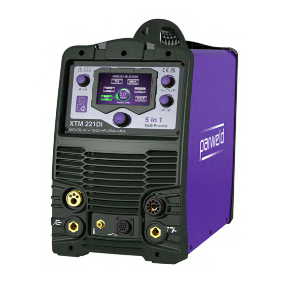
Page 5: Product Description
Wear oil-free protective garments such as leather gloves, heavy shirt, cuffless trousers, high shoes, and a cap. Remove any The XTM 221Di is a multi-mode welding machine using inverter combustibles, such as a butane lighter or matches, from your person technology. -
Page 6: Technical Specifications
110V input 230V input 100% 100% 140A 100A 200A 140A 110A The XTM 221Di, is a compact type machine with integrated wire feed unit for use with single phase 110/230V supply with smart 100% 100% input switching. 140A 100A 200A 130A... -
Page 7: Input And Grounding Connection
11. Multifunction Control Knob 12. Amperage / Wire Speed Adjustment 13. Voltage / Downslope / Arc Force Adjustment 14. Inductance / Post Gas Control 15. Digital Display 16. TIG Torch Gas Connector 17. TIG Torch Trigger Connector 18. Plasma torch connector www.parweld.com... -
Page 8: Operation
Press and hold to step back in menu tree Short press at end of menu returns to start menu 6.2 Language of Operation TIG Synergic TIG Welding Setup MMA Synergic MMA Welding Setup Plasma Cutting setup Short Press (1 sec) to return to start menu www.parweld.com... -
Page 9: Mig Welding Preparing The Machine
MIG Torch Installation Your Parweld MIG/MAG Welding Torch has been supplied ready to weld. It has been supplied with the standard consumables denoted in the product brochure. To connect the torch to the power source: 1. -
Page 10: Setting The Machine For Welding
Adjusted on screen from the Help Menu. Soft start The machine has a pre-set soft start system. 7.0 Setting the Machine for Welding 7.1 MIG Torch Selection Select the HELP menu from the main Process Selection screen and follow the screen prompts as follows. www.parweld.com... -
Page 11: Mig Man - Manual Mig Welding
MIG MAN Follow the screen prompts to complete the machine setup. Example setting. Adjust by Pressing Torch Buttons on the Handle. Parameter Scroll Torch with OLED Display Down Parameter Scroll Parameter Scroll Torch with 4 Button Control Down Parameter Scroll www.parweld.com... -
Page 12: Mig Welding Procedure
Follow the screen prompts to complete the machine setup. Example setting. 7.7 TIG Welding Follow the screen prompts to complete the machine set up. 7.7.1 TIG Torch Selection Select the HELP menu from the main Process Selection screen and follow the screen prompts as follows. www.parweld.com... -
Page 13: Tig Torch Installation
Auto Set allows rapid setting of the machine based on material type and thickness, with HF starting. Auto Set Example Adjust downslope and post flow to user preference using the knobs on the right of the screen. Manual Set Example www.parweld.com... - Page 14 Not all functions are available in 2T mode. DC Without Pulse. Press Release Post Gas Pre Gas DC With Pulse. 2T mode Current Adjustment Release Release Press Press www.parweld.com Initial Final Current Current Post Gas Pre Gas...
-
Page 15: Tig Welding Guide
(Note in 4T position you must press and release to start the process and press and release again to stop the process). 1/16 (1.6mm) 60-120 75-150 3/32 (2.4mm) 100-180 150-250 Tungsten electrode types Type Application Colour Thoriated 2% DC welding of mild steel, www.parweld.com Stainless steel and Copper... -
Page 16: Ac Tig Welding (No Pulse)
10) Rotate the control knob to move the LED to the initial current (C) This can be adjusted from 5 to 100% of the main welding current. The value is displayed on the digital display (B). 50% is a good initial setting. Note this function only operates in 4T switch mode. www.parweld.com... -
Page 17: Tig Welding (With Pulse)
14) Rotate the control knob to move the LED to the final current (G) This can be adjusted from 5 to 100% of the main welding current. The value is displayed on the digital display (B). 10% is a good initial setting. Note this function only operates in 4T switch mode. www.parweld.com... -
Page 18: Plasma Cutting
You are now ready to operate. On the following example screen, the air pressure quoted is the suggested air pressure for the parameters Switch on the machine and return to the home menu, then select the selected. Adjust the regulator inside the machine to match this. Plasma Cut option. www.parweld.com... -
Page 19: Mesh Cutting
15 second post-flow will occur. If the torch switch is closed during the post-flow, the cutting arc will restart after switching off the air. Refer to the flow chart below for the operating sequence. Press Cutting Release trigger trigger stops Cutting stops air flows for 15 seconds www.parweld.com... -
Page 20: Saving To Memory
Connect the MIG, TIG and Plasma torches as previously described. Ensure all gas types are connected to the rear of the machine. Set the machine from the main menu for the MIG,TIG and Plasma as required. Switching the process. Press the torch trigger briefly to select the process. www.parweld.com... -
Page 21: Fault Finding
Adjust work angle or widen groove to access bottom during welding. Momentarily hold arc on groove side walls when using weaving technique. Keep arc on leading edge of weld puddle. Use correct gun angle of 0 to 15 degrees. www.parweld.com... -
Page 22: Mig Welding Problems
Dirty welding wire. Use clean, dry welding wire. Eliminate pickup of oil or lubricant on welding wire from feeder or liner. Wire feed unit operates but no Gas cylinder empty gas flow . Gas regulator closed Faulty solenoid Restriction in torch cables www.parweld.com... -
Page 23: Mma Welding Problems
(d) Travel speed of current electrode is too high (c) Adjust (e) Scale or dirt on joint angle so the surface welding arc is directed more into the base metal (d) Reduce travel speed of electrode (e) Clean surface before welding. www.parweld.com... -
Page 24: Tig Welding Problems
(g) The electrode is too (e) Turn on small for the welding (f) Turn on current (g) Increase electrode diameter or reduce the welding current Poor weld finish Inadequate shielding Increase gas flow or check gas line for gas flow problems www.parweld.com... -
Page 25: Plasma Cutting Problems
5Bar. Restart the illuminates when trigger power source pressed Interlock light Outer nozzle or other re-assemble front flashes when consumable not installed end spares to trigger pressed correctly ensure outer nozzle is seated fully. Restart the power source www.parweld.com... -
Page 26: Control Torch Schematic
9.0 Control Torch Schematic ® Pro-Grip Control 250A Air Cooled MIG Torch 230A CO , 200A Mixed Gas @ 60% Duty Cycle, EN60974-7 .030"-.045"/0.8mm to 1.2mm Wires Pro-Grip Max parweld.com @ParweldLtd ParweldTV parweld_uk ® Components Models * Denotes Standard Build... - Page 27 Steel Liner .040"-.045"/1.0mm-1.2mm x 5m B1536-30 Teflon Liner .023"-.035"/0.6mm-0.9mm x 3m B1536-40 Teflon Liner .023"-.035"/0.6mm-0.9mm x 4m B1536-50 Teflon Liner .023"-.035"/0.6mm-0.9mm x 5m B2513-30 Teflon Liner .040"-.045"/1.0mm-1.2mm x 3m B2513-40 Teflon Liner .040"-.045"/1.0mm-1.2mm x 4m B2513-50 Teflon Liner .040"-.045"/1.0mm-1.2mm x 5m www.parweld.com...
-
Page 28: Accessories
" BSP inlet and outlet connections. Stock Code Description 706101 Flow Meter Mixed Gas 25 lpm (MIG) 706100 Flow Meter 0-12 lpm (TIG) Gas flow Tester Designed to check gas flow at the front of MIG Torches. Stock Code Description 806001 Gas flow Tester www.parweld.com... -
Page 29: Ec Declaration Of Conformity
11.0 EC Declaration of Conformity Hereby we declare that the machines as stated below Type: XTM 221Di Conform to the EC Directives: Low Voltage Directive 2014/35/EEC EMC Directive 2014/35/EEC Harmonised European standard: EN/IEC 60974-1 This is to certify that the tested sample is in conformity with all provisions of the above detailed EU directives and product standards. -
Page 30: Weee Statement
The warranty is effective from the date that the authorized Distributor delivers the products to the purchaser. Not withstanding the foregoing, in no event shall the warranty period extend more than the time stated plus one month from the date Parweld delivered the product to the authorized distributor. - Page 31 www.parweld.com...
- Page 32 Parweld Limited Bewdley Business Park Long Bank Bewdley Worcestershire England DY12 2TZ Tel. +44 1299 266800 Fax. +44 1299 266900 www.parweld.com info@parweld.co.uk...
Need help?
Do you have a question about the XTM 221Di and is the answer not in the manual?
Questions and answers