Advertisement
Quick Links
Installation, Precautions & Servicing
This product is only suitable for well insulated spaces or occasional use
MODEL:
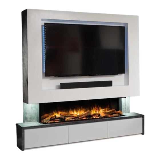
Geo 1500 Media Wall
Important
Please bear in mind the weight of the fire before removal from the packaging and installation.
Consider if help is required.
Carefully remove the fire from the packing checking neither the heater nor the power cable has been
damaged during transport. Do not operate the fire if damaged.
The accessories are found in a box that is packed at the side of the fire.
Always read this manual first before attempting to install or use and keep in a safe place.
Your fire is guaranteed for three years from the date of purchase.
ALL INSTRUCTIONS MUST BE HANDED TO END USER FOR SAFE KEEPING
Advertisement

Subscribe to Our Youtube Channel
Related Manuals for Flamerite Fires E-FX Geo 1500 Media Wall


Summary of Contents for Flamerite Fires E-FX Geo 1500 Media Wall
- Page 1 Installation, Precautions & Servicing This product is only suitable for well insulated spaces or occasional use MODEL: Geo 1500 Media Wall Important Please bear in mind the weight of the fire before removal from the packaging and installation. Consider if help is required. Carefully remove the fire from the packing checking neither the heater nor the power cable has been damaged during transport.
- Page 2 Contents Important Safety Information and Warnings UCKA Declaration CE Declaration Technical Specification Installation Instructions Non Reflective Rear Screen Option Fuel Effects Glass Fitting & Removal Information Requirements Maintenance & Trouble Shooting Wiring Diagrams Recycling Registration No WEE/DH1656ZW In accordance with European Directive 2012/19/ EU, waste electrical and electronic equipment (WEEE) must not be disposed of with household waste.
- Page 3 Product Type: Electric Fire (fan heater) Requirements: BS-EN 60335-2-30:2009 + A11:2012 BS-EN 60335-1:2012 + A11:2014 + A13:2017 + A1:2019 + A14:2019 + A2:2019 BS-EN 55014-1:2017 BS-EN 55014-2:2015 BS-EN61000-3-2:2014 BS-EN 61000-3-3:2013 Manufactured by: Flamerite Fires Ltd. Greenhough Road, Lichfield. Staffs. WS13 7AU. UK...
- Page 4 EN 55014-1:2017 EN 55014-2:2015 EN61000-3-2:2014 EN 61000-3-3:2013 Manufactured by: Flamerite Fires Ltd. Greenhough Road, Lichfield. Staffs. WS13 7AU. UK Technical Specification Manufactured by: Flamerite Fires Ltd. Greenhough Road, Lichfield. Staffs. WS13 7AU. UK A 230V 13A 50Hz supply is required.
- Page 5 Installation Instructions WARNING DO NOT TWIST, FORCE OR SQUEEZE THE FIRE DURING THE INSTALLATION PROCESS, AS THIS MAY DEFORM THE CASE STOPPING THE GLASS FROM MOVING CORRECTLY. THE COMPLETE UNIT MUST BE WELL SUPPORTED IN OR ON ANY STRUCTURE. NEVER SECURE TO JUST PLASTER BOARD ALONE.
- Page 6 2mm above the top Place the fire into the drawer unit and push into position against the wall. Mark a line of the upper bracket and remove the drawer unit again. This is the exact point for fitting all other brackets and allows for the drawer unit to slide under easily to complete the fitting.
- Page 7 Fire Upper Bracket: Fixings 60mm screws M10 rawl plugs 13mm screws Secure the fire onto the brackets A second person will be required. Leave the upper bracket attached. Place and hold the fire onto the lower bracket keeping it firmly pressed against the wall. Check the upper bracket aligns with your original datum line and mark the fixing holes through the bracket onto the wall.
- Page 8 Top Unit Fixings M6 x 60mm screws M6 Washers Rawl plugs From the top of the upper fire bracket, measure and mark a level line at 535 mm and 1005 mm. With the highest edge facing forwards and the lowest edge against the wall, mark up and fix the top unit brackets with the bottom of each bracket level with those lines.
- Page 9 Securing the top unit into position WARNING ANY WEIGHT ON THE TOP OF THE FIRE MAY CAUSE ISSUES WHEN INSERTING, REMOVING OR USING THE GLASS. A second person will be required. Now the fire and top brackets are secured into position, the media wall may be assembled.
- Page 10 Securing the drawer unit into position Push the drawer unit back under the fire but stop short so you may add the side trims and feed the power cable from the top unit into the base. Insert the plug into the three pin socket. Switch on. Plug the lead from that three pin socket into the wall socket.
- Page 11 Magnetic Side Panels & Décor Trim left side panel will hide the power cable coming down from the top unit. Fit both sides. Push the draw unit up against the wall. Using four 13mm screws, secure to the fire along both side flanges. Place your décor trims over the front and side channel to provide a neat finish, they are held in place with magnets.
- Page 12 Anti-Lift Securing Block Remove the centre of the top unit by removing the six screws, unplug the flexi LED. Fit the anti-lift securing block above the lower top unit wall bracket using the final two M6 fasteners.
- Page 13 Non Reflective Rear Screen Option As standard one of the two rear screens in the fire has a reflective coating to mirror the log effect. When the fire is on, the flame simulates a 3 dimensional burn between the actual log effect and the reflection generated by the coating.
- Page 14 Using the foam tape provided in the accessory pack, apply across the length of the top bracket’s front face to keep the projection screen secure. Now the reflective glass screen has been removed, screw the top bracket back into place and add the projection screen. Place the fuel bed back into the fire, reconnect the cable A underneath and replace both the screws at either side.
- Page 15 Glass Fitting & Removal We recommend two persons to fit the EFX 1500 & 1800 glass Fitting the front glass Using the images below, push the side glass (A) back towards the rear of the case. You will notice a long gap on the underside of the opening in front of the heater grills.
- Page 16 0.0005 0.005 0.0005 Type of heat output/ room temperature control With distance control option Room temperature control, with open window detection Adaptive Start With electronic room temperature control plus week timer Contact Details: Flamerite Fires Ltd. WS13 7AU. UK. www.flameritefires.com...
- Page 17 Maintenance & Trouble Shooting WARNING BEFORE ANY MAINTENANCE IS UNDERTAKEN, ALWAYS DISCONNECT THE FIRE FROM THE MAINS POWER SUPPLY. Maintenance must be undertaken by a Flamerite service engineer or similarly qualified persons in order to avoid a hazard. Replacements part are available from www.flameritefires.com PROBLEM POSSIBLE CAUSE SOLUTION...
- Page 18 Wiring Diagrams Fire...
- Page 19 Top Unit Bottom Unit...
- Page 20 Manufactured by Flamerite Fires Ltd Greenhough Road, Lichfield. Staffordshire. WS13 7AU. UK +441543 251122 info@flameritefires.com...
Need help?
Do you have a question about the E-FX Geo 1500 Media Wall and is the answer not in the manual?
Questions and answers