Table of Contents
Advertisement
Quick Links
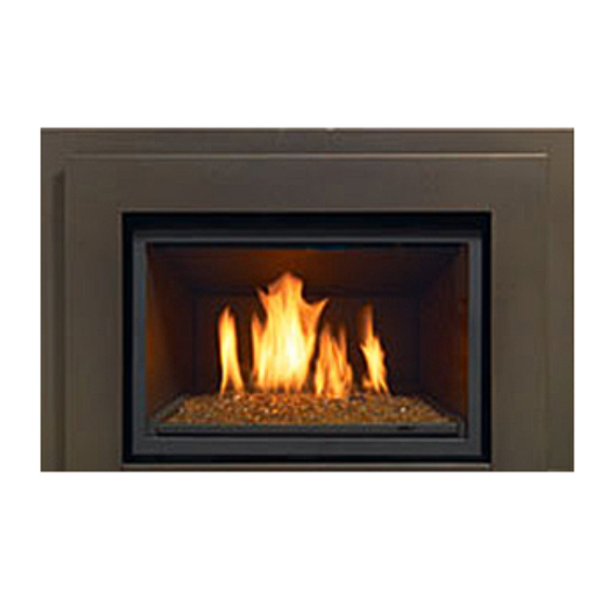
L540E / HZI540E Gas Insert
MODELS: L540E-NG1 Natural Gas
HZI540E-NG1 Natural Gas
WARNING:
Improper installation, adjustment, alteration, service or
maintenance can cause injury or property damage. Refer to
this manual. For assistance or additional information consult
an authorized installer, service agency or the gas supplier.
FOR YOUR SAFETY
Do not store or use gasoline or other fl ammable vapours and
liquids in the vicinity of this or any other appliance.
Installation and service must be performed by an authorized
installer, service agency or the gas supplier.
Tested by:
919-100b
L540E-LP1 Propane
HZI540E-LP1 Propane
Installer: Please complete the details on the back cover
and leave this manual with the homeowner.
Homeowner: Please keep these instructions for future reference.
FPI FIREPLACE PRODUCTS INTERNATIONAL LTD. 6988 Venture St., Delta, BC Canada, V4G 1H4
Owners &
Installation Manual
www.regency-fi re.com
FOR YOUR SAFETY
What to do if you smell gas:
Do not try to light any appliance
Do not touch any electrical switch:
do not use any phone in your
building.
Immediately call your gas supplier
from a neighbour's phone. Follow
the gas supplier's instructions.
If you cannot reach your gas
supplier, call the fi re department.
02/27/03
Advertisement
Table of Contents

Subscribe to Our Youtube Channel
Related Manuals for Regency Fireplace Products L540E-NG1


Summary of Contents for Regency Fireplace Products L540E-NG1
- Page 1 Owners & L540E / HZI540E Gas Insert Installation Manual www.regency-fi re.com MODELS: L540E-NG1 Natural Gas L540E-LP1 Propane HZI540E-NG1 Natural Gas HZI540E-LP1 Propane WARNING: FOR YOUR SAFETY Improper installation, adjustment, alteration, service or What to do if you smell gas: maintenance can cause injury or property damage. Refer to Do not try to light any appliance this manual.
- Page 2 TO THE NEW OWNER Congratulations! You are the owner of a state-of-the-art Gas Insert by Regency. The Regency Gas Insert Series of hand crafted appliances has been designed to provide you with all the warmth and charm of a fi replace, at the fl ick of a switch. The models L540E / HZI540E of this series have been approved by Warnock Hersey for both safety and effi...
-
Page 3: Dimensions
DIMENSIONS UNIT DIMENSIONS 4 " 856.58 8 " 626.91 2 " 1155.45 8 " 1011.43 8 " 798.02 8 " 8 " 715.47 257.80 L540E / HZI540E Direct Vent Gas Insert... - Page 4 DIMENSIONS 45-1/2" 1155.45 Dimensions w/4 sided Faceplate 46" 1168mm 8 " 1011mm Dimensions w/Oversized Faceplate 2 " 1155.70 2 " 495.30 4 " 349.25 Dimensions w/Full Screen Doors L540E / HZI540E Direct Vent Gas Insert...
-
Page 5: Table Of Contents
TABLE OF CONTENTS SAFETY LABEL Brick panel installation ..........29 Enamel panel installation..........30 Glass door removal / installation .........31 Copy of the Safety Label ..........5 3 sided low profi le faceplate installation ......32 4 sided low profi le faceplate installation ......33 DIMENSIONS Oversize faceplate installation ........34 Optional Hearth Trim installation .........35... - Page 6 é Tested to: CAN/CGA-2.17-M91(R2009) ANSI Z21.88-2009/CSA 2.33-2009 Serial No. / No de serie 4001172 NATURAL GAS FIREPLACE INSERT: MODEL L540E-NG1 É QUIP A L'UISINE POUR GAZ NATURAL É MODEL L540E-NG1 Factory Equipped For Altitude 0-4500ft. (0-1370m) Min. supply pressure 5“...
- Page 7 SAFETY LABEL This is a copy of the labels that accompany each HZI540E Gas Insert. NOTE: Regency units are constantly being improved. Check the We have printed a copy of the contents here for your review. label on the unit and if there is a difference, the label on the unit is the correct one.
-
Page 8: Requirements
REQUIREMENTS MA Code - CO Detector (for the State of Massachusetts only) 5.08: Modifications to NFPA-54, Chapter 10 (2) Revise 10.8.3 by adding the following additional requirements: (a) For all side wall horizontally vented gas fueled equipment installed in every dwelling, building or structure used in whole or in part for residential purposes, including those owned or operated by the Commonwealth and where the side wall exhaust vent termination is less than seven (7) feet above finished grade in the area of the venting, including but not limited to decks and porches, the following requirements shall be satisfied:... -
Page 9: Important Message
INSTALLATION IMPORTANT MESSAGE YOUNG CHILDREN SHOULD BE CARE- FULLY SUPERVISED WHEN THEY ARE SAVE THESE IN THE SAME AREA AS THE APPLI- INSTRUCTIONS ANCE. TODDLERS, YOUNG CHILDREN AND OTHERS MAY BE SUSCEPTIBLE The L540E / HZI540E Gas Inserts must be installed TO ACCIDENTAL CONTACT BURNS. -
Page 10: Important Message
INSTALLATION IMPORTANT MESSAGE General Safety Information GAS PRESSURE SAVE THESE TESTING 1) The appliance installation must conform with local codes or in the absence of local INSTRUCTIONS codes, with CAN/CGA B149 (in Canada) or The appliance must be isolated from the gas the National Fuel Gas Code ANSI Z223.1 in supply piping system by closing its individual The Regency Gas Insert must be installed in... -
Page 11: Installation Checklist
INSTALLATION INSTALLATION MINIMUM FIREPLACE 12) Final check: Before leaving this unit with the CHECKLIST customer, the installer must ensure that the DIMENSIONS appliance is fi ring correctly. This includes: Before installing vent system ensure that the damper The minimum fi replace clearances & dimensions a) Clocking the appliance to ensure the correct plate is open and secure to prevent the damper plate for the Regency gas insert are shown in the... -
Page 12: Minimum Clearances To Combustibles
INSTALLATION MINIMUM CLEARANCES TO COMBUSTIBLES The clearances listed below are Minimum distances unless otherwise stated: A major cause of fi res is failure to maintain required clearances (air space) to combustible materials. It is of the greatest importance that this decorative gas appliance be installed only in accordance with these instructions. -
Page 13: Gas Connection
INSTALLATION GAS CONNECTION The Air Intake and exhaust pipes must be attached to the inlet and exhaust collars of the termination cap with a minimum of three screws per pipe. GAS CONNECTION WARNING: Only persons licensed to work Part # Description with gas piping may make the 948-305... -
Page 14: Flue / Vent Installation
INSTALLATION FLUE / VENT INSTALLATION 4) Use the Flue Connector Slide Tool to slowly pull the Flue Connector NOTE: Flue Plate Connector Gasket Plate forward as you move the Insert rearward into the Fireplace Chase. must not be damaged or removed. Care must be taken to ensure that this gasket remains intact to prevent fl... -
Page 15: Leveling Leg Adjustment
INSTALLATION LEVELING LEG ADJUSTMENT The L540E / HZI540E inserts are equipped with 4 levelling legs that are accessible while the appliance is in its fi nal installation position. The unit can be adjusted up to 5/8" (16mm). The faceplate must not be installed to do this adjustment, if installed, remove faceplate. Remove left and right inner panels by sliding them forward. -
Page 16: Air Shutter Adjustment
INSTALLATION AIR SHUTTER ADJUSTMENT Air Shutters are required to increase or decrease the amount of air that is mixed with the fuel before combustion. This will have an affect on how well the fuel combusts and how the fl ame physically appears. Low primary air will leave a taller, yellower fl... -
Page 17: High Elevation
INSTALLATION 885 S.I.T. VALVE L540E-NG / HZI540E-NG Burner SYSTEM DATA DESCRIPTION Flame Sensor Min. Supply Pressure 5" WC (1.25 kpa) 1) 6 Stage fl ame adjustment Manifold Pressure 3.5" WC (0.87 kpa) 2) Pilot adjustment Orifi ce Size #32 DMS 3) Outlet Pressure Tap Maximum Input 38,000 Btu/h... -
Page 18: Conversion From Ng To Lp
INSTALLATION CONVERSION FROM NG TO LP L540E/HZI540E using SIT 885 NOVA Gas Valve THIS CONVERSION MUST BE DONE BY A QUALIFIED GAS FITTER IF IN DOUBT DO NOT DO THIS CONVERSION! WARNING This conversion kit shall be installed by a qualifi ed service agency in accordance with the manufacturer’s instructions and all applicable codes and requirements of the authority having jurisdiction. - Page 19 INSTALLATION 6) Re-attach the Pressure Regulator wire, and re-situate the Gas Valve, Pilot Orifi ce – PSE Pilot Equipped Systems secure the screws that fasten the Gas Valve Mounting Brackets. 7) Remove burner (see burner removal section in manual). 8) Loosen and remove the pilot target hex fi tting with a 7/16 wrench as shown below.
-
Page 20: Profl Ame Remote System Gtmf With Fan
INSTALLATION PROFLAME REMOTE SYSTEM GTMF WITH FAN (L540E / HZI540E) WIRING DIAGRAM Proflame System Configuration 886 GTMF Wire Diagram SureFire™ Switch 0.584.907 Thermostat See optional wall thermostat (Optional) installation in this manual. Ground Black Neutral Green Live Fan Thermodisc Ground 120V AC 60 Hz (normally open) -
Page 21: Optional Wall Thermostat Installation
INSTALLATION OPTIONAL WALL THERMOSTAT INSTALLATION This installation must be completed during initial install with the side access panel removed. A wall thermostat may be installed if desired. Recommended: Mount thermostat beside unit receiver. 1) Run wires from thermostat into the unit using the appropriate wire gauge - see chart below. Thermostat Wire Table Recommended Maximum Lead Length (Two-Wire) When Using Wall... -
Page 22: Glass Crystal / Ceramic Spa Stone Installation
INSTALLATION GLASS CRYSTAL / CERAMIC SPA STONE INSTALLATION Evenly spread the Glass Crystals or optional Ceramic Spa Stones over the burner. Ensure the crystals (or stones) do not overlap too much as this will effect the fl ame pattern. IMPORTANT NOTE: Only the supplied approved Glass Crystals and Ceramic Spa are to be used with these fi... - Page 23 INSTALLATION CAUTION DO NOT place spa stones over pilot and burner ports. L540E / HZI540E Direct Vent Gas Insert...
-
Page 24: Optional Pebbles / Glass Crystal Installation
INSTALLATION OPTIONAL PEBBLES / GLASS CRYSTAL INSTALLATION FOR FIREBOX BASE (AROUND BURNER) Firebox (Around Burner) Packages Unit Glass Crystals Pebbles HZ54E / HZ54EPV 6 lbs 2 packages (6 x bags pebbles) HZ42 / HZ42E / HZ40E 5 lbs 2 packages (6 x bags pebbles) HZ42ST / HZ42STE / HZ42STEPV 5 lbs 2 package (6 x bags pebbles) HZ30E... -
Page 25: L540E Log Set Installation
INSTALLATION L540E LOG SET INSTALLATION L540E Log Set up Video Read the instructions below carefully and refer to the images. If the logs are broken do not use the unit until they are replaced. Broken logs can interfere with pilot operation. Improper positioning of the logs may create carbon build-up and can alter the unit's performance which is not covered under warranty. - Page 26 INSTALLATION 6) Log 2 should lean against Log 1 - as shown below. 9) Ensure the contour of Log 4 matches up the burner contour and does not rock when seated. Log 2 in position 7) Locate provisions in the bottom of Log 3 (see highlighted areas below)and place provisions on burner.
- Page 27 INSTALLATION 13) Locate provision on the bottom of Log 7 (see highlighted areas), place on provision on Log 1 and in provisions on Log 2 and Log 4 (see darkened areas). 11) Locate provisions in the bottom of Log 6 (see highlighted areas) and place provisions on Log 1 and Log 5 (see darkened areas).
-
Page 28: Standing Pilot And Heat Exchange Return
INSTALLATION STANDING PILOT AND HEAT EXCHANGE RETURN The L540E / HZI540E use a heat exchanger and effi cient combustion INSTALLING THE HEAT EXCHANGER RETURN technology to provide extreme heating effi ciencies. The more effi cient an ap- pliance becomes, the lower the fl ue gas temperatures becomes. 1) Remove the left and right side panels. -
Page 29: Brick Panel Installation
INSTALLATION BRICK PANEL INSTALLATION Brick panels are soft and fragile. Use caution when handling the panels, 3) Using a screw driver, loosen the fasteners holding the Firebox Liner Re- being careful not to jar them or scratch the painted surfaces. tainers and move them towards the center of the fi... -
Page 30: Enamel Panel Installation
INSTALLATION ENAMEL PANEL INSTALLATION 1a) (L390E/L390EB/HZI390E/HZI390EB only) Before you Start: Remove fi ller sections from right and left sides of burner and discard - see below. Black Enamel Panels ( L540EB/HZI540EB only) • Black Enamel panels must be inspected for scratches and dimples prior Remove metallic black left and right side inner panels by sliding to installation. -
Page 31: Glass Door Removal / Installation
INSTALLATION GLASS DOOR REMOVAL / INSTALLATION WARNING: Do not operate the appliance with the glass panels removed, cracked or broken. Replacement of the glass panels should be done by a licensed or qualifi ed service person. 1) Insert the door tool into the lower door latch. Upper Door Hooks Window Clip (x4) Door Frame... -
Page 32: Sided Low Profile Faceplate Installation
INSTALLATION 3 SIDED LOW PROFILE FACEPLATE INSTALLATION Note: A mantel defl ector may be installed to reduce the minimum mantel height. 4) Install front faceplate and secure to the unit with 4 screws in location Refer to minimum clearances in the installation manual. shown below. -
Page 33: Sided Low Profi Le Faceplate Installation
INSTALLATION 4 SIDED LOW PROFILE FACEPLATE INSTALLATION Note: A mantel defl ector may be installed to reduce the minimum mantel height. 4) Install front faceplate and secure to the unit with 4 screws in locations Refer to minimum clearances in the installation manual. shown below. -
Page 34: Oversize Faceplate Installation
INSTALLATION OVERSIZE FACEPLATE INSTALLATION 3. Install lower trim piece oriented as shown below. Note: Faceplate may be installed after the unit is in it's fi nal position. 1. Install Low Profi le faceplate backing plate and secure to the unit with 4 screws in locations shown below. -
Page 35: Optional Hearth Trim Installation
INSTALLATION OPTIONAL HEARTH TRIM INSTALLATION Hearth Trim is an option that can be used to fi nish off the installation when the bottom of the fi replace is higher than the hearth or to raise the fi replace. ** If no screw holes are present. 1) For units L390E/HZI390E/L540E/HZI540E–remove 4 screws in locations shown below to remove outer faceplate. -
Page 36: Optional Screen Installation
INSTALLATION OPTIONAL SCREEN INSTALLATION 1) Install the optional screen by hooking the top of the screen over the two tabs at the top of the glass door. Locations shown in the diagrams below. Tabs 2) Secure the screen by placing provided magnets between the back of the screen and the unit in locations shown below. -
Page 37: Optional Full Screen Door Installation
INSTALLATION OPTIONAL FULL SCREEN DOOR INSTALLATION Note: A mantel defl ector may be installed to reduce the minimum mantel height. 4) Install the optional full screen doors onto the frame. Refer to minimum clearances in the installation manual. If not installing the mantel defl ector - proceed to step 3. 1) Line up the mantel defl... -
Page 38: Operating Instructions
OPERATING INSTRUCTIONS OPERATING LIGHTING FIRST FIRE INSTRUCTIONS PROCEDURE The fi rst fi re in your stove is part of the paint curing process. To ensure that the paint is properly cured, Before operating this appliance, proceed through IMPORTANT it is recommended that you burn your fi replace for the following check list. -
Page 39: Normal Operating Sounds Of Gas Appliances
OPERATING INSTRUCTIONS NORMAL OPERATING COPY OF LIGHTING INSTRUCTION PLATE SOUNDS OF GAS APPLIANCES FOR YOUR SAFETY READ BEFORE LIGHTING This appliance must be installed in accordance with local codes, if any; if none, follow the National Fuel Gas Code, ANSI Z223.1/NFPA 54, or It is possible that you will hear some sounds from Natural Gas and Propane Installation Codes, CSA B149.1. -
Page 40: Maintenance
MAINTENANCE MAINTENANCE DOOR GLASS WARNING: CHILDREN AND ADULTS SHOULD BE ALERTED TO THE HAZARDS INSTRUCTIONS Your Regency insert is supplied with high OF HIGH SURFACE TEMPERATURE AND temperature, Neoceram ceramic glass that will SHOULD STAY AWAY TO AVOID BURNS 1) Always turn the gas valve to off before cleaning. withstand the highest heat that your unit will produce. -
Page 41: Pilot Adjustment
MAINTENANCE GENERAL VENT PILOT ADJUSTMENT MAINTENANCE Periodically check the pilot fl ames. Correct fl ame pattern has two strong blue fl ames: 1 fl owing Conduct an inspection of the venting system semi- around the fl ame sensor and 1 fl owing across annually. -
Page 42: Glass Crystal Burner Removal / Installation
MAINTENANCE GLASS CRYSTAL BURNER REMOVAL / INSTALLATION (HZI540E) 4) Lift out the burner by raising the front and pulling the burner towards you. Disconnect unit from gas supply and allow unit to cool before removing The mixing tube will slide out of the burner mounting bracket at the rear. burner. -
Page 43: L540E Ceramic Burner Removal / Installation
MAINTENANCE L540E CERAMIC BURNER REMOVAL / INSTALLATION REMOVAL INSTALLATION 1) Remove left and right side panels by sliding them forward - see below. Care must be taken when installing the burner into the fi rebox. Do not damage, knock or scrape the pilot assembly. The fl... -
Page 44: Fan Maintenance - With Gtmf Remote Control
MAINTENANCE FAN MAINTENANCE - WITH GTMF REMOTE CONTROL Note: To access the side and rear access panels both the gas and venting 4) Remove 3 screws and remove the fan from the unit as shown below. will need to be disconnected(see vent/fl ue installation in this manual) for proper removal. -
Page 45: Valve Replacement
MAINTENANCE VALVE REPLACEMENT Before you begin: 5) Disconnect the Pilot Supply Line from the Gas Valve * Shut off the gas supply to the unit. Disconnect all electrical supply to the unit. Always let the appliance cool to room temperature before servicing. Remove unit fl... - Page 46 MAINTENANCE 11) There is a provision in the Valve body casting that is designed to be 8) Remove the Gas Valve by lifting upwards and outwards. used as a gripping point for assembly with other components. This is the portion of the valve that can be placed in a machine vice. 9) Secure the Valve Assembly by the 90 Elbow Fitting in a sturdy table vice.
-
Page 47: Parts List
PARTS LIST MAIN ASSEMBLY Part # Description Part # Description 296-018 Flue Connector Gasket 911-012 Ignition Board (DBC) SIT IPI 0.584.302 296-113 Flue Connector 396-031 Bracket Valve Mounting Lh/Rh 396-042 Slide / Door Tool 911-085 Valve LP 885 SIT IPI 0.885.002 296-010 Exhaust Baffl... - Page 48 PARTS LIST L540E / HZI540E Direct Vent Gas Insert...
-
Page 49: Low Profile Faceplate
PARTS LIST LOW PROFILE FACEPLATE Part # Description 296-922 3 Sided Faceplate Low Profi le Sunset Bronze 296-102 3 Sided Faceplate Low Profi le Black 296-130 3 Sided Faceplate Low Profi le Iron Gray 296-129 3 Sided Faceplate Low Profi le Custom 296-127 Faceplate 4-Sided Low Profi... - Page 50 NOTES L540E / HZI540E Direct Vent Gas Insert...
-
Page 51: Warranty
WARRANTY Regency Fireplace Products are designed with reliability and simplicity in mind. In addition, our internal Quality Assurance Team carefully inspects each unit thoroughly before it leaves our facility. FPI Fireplace Products International Ltd. is pleased to extend this limited lifetime warranty to the original purchaser of a Regency Product. - Page 52 ® Register your Regency warranty online www.regency-fi re.com Reasons to register your product online today! • View and modify a list of all your registered products. • Request automatic email notifi cation of new product updates. • Stay informed about the current promotions, events, and special offers on related products.
Need help?
Do you have a question about the L540E-NG1 and is the answer not in the manual?
Questions and answers