Table of Contents
Advertisement
Quick Links
Model No. NTEX14921-INT.0
Serial No.
Write the serial number in the space
above for reference.
MEMBER CARE
UNITED KINGDOM
Call: 0330 123 1045
From Ireland: 053 92 36102
Website: iconsupport.eu
E-mail: csuk@iconeurope.com
Write:
ICON Health & Fitness, Ltd.
Unit 4, Westgate Court
Silkwood Park
OSSETT
WF5 9TT
UNITED KINGDOM
AUSTRALIA
Call: 1800 993 770
E-mail: australiacc@iconfitness.com
Write:
iFIT Inc.
PO Box 635
WINSTON HILLS NSW 2153
AUSTRALIA
CAUTION
Read all precautions and
instructions in this manual before
using this equipment. Keep this
manual for future reference.
Serial
Number
Decal
USER'S MANUAL
iconeurope.com
Advertisement
Table of Contents

Related Manuals for NordicTrack NTEX14921-INT.0


Summary of Contents for NordicTrack NTEX14921-INT.0
- Page 1 Model No. NTEX14921-INT.0 Serial No. USER’S MANUAL Write the serial number in the space above for reference. Serial Number Decal MEMBER CARE UNITED KINGDOM Call: 0330 123 1045 From Ireland: 053 92 36102 Website: iconsupport.eu E-mail: csuk@iconeurope.com Write: ICON Health & Fitness, Ltd.
-
Page 2: Table Of Contents
Apply the decal in the location shown. Note: The decal(s) may not be shown at actual size. NORDICTRACK and IFIT are registered trademarks of iFIT Inc. The Bluetooth ® word mark and logos are regis- tered trademarks of Bluetooth SIG, Inc. and are used under license. Google Maps is a trademark of Google LLC. -
Page 3: Important Precautions
IMPORTANT PRECAUTIONS WARNING: To reduce the risk of serious injury, read all important precautions and instructions in this manual and all warnings on your exercise bike before using your exercise bike. iFIT assumes no responsibility for personal injury or property damage sustained by or through the use of this product. -
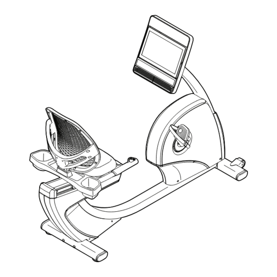
Page 4: Before You Begin
BEFORE YOU BEGIN Thank you for selecting the revolutionary reading this manual, please see the front cover of this NORDICTRACK ® R 35 exercise bike. Cycling is an manual. To help us assist you, note the product model effective exercise for increasing cardiovascular fi tness, number and serial number before contacting us. -
Page 5: Part Identification Chart
PART IDENTIFICATION CHART Use the drawings below to identify the small parts needed for assembly. The number in parentheses below each drawing is the key number of the part, from the PART LIST near the end of this manual. The number following the key number is the quantity needed for assembly. -
Page 6: Assembly
ASSEMBLY • Assembly requires two persons. In addition to the included tool(s), assembly requires the following tools: • Place all parts in a cleared area and remove the one Phillips screwdriver packing materials. Do not dispose of the packing materials until you fi nish all assembly steps. one adjustable wrench •... - Page 7 3. Set a sturdy piece of packing material under the front of the Frame (1). Have a second person hold the Frame to prevent it from tipping while you complete this step. Orient the Front Stabilizer (15) as shown. Attach the Front Stabilizer to the Frame (1) with two M10 x 122mm Screws (65).
- Page 8 5. Tip: Avoid pinching the wires. Slide the Upright (2) onto the Frame (1). Attach the Upright (2) with four M10 x 62mm Screws (70); start all the Screws, and then tighten them. Avoid pinching the wires 6. Press the mount on the Front Shield (58) into the Frame (1).
- Page 9 7. Orient the Upright Cover (57) as shown. Hold the Upright Cover near the Upright (2), and insert the wire tie (A) and the wires (B) upward through the Upright Cover. Then, slide the Upright Cover (57) onto the Upright (2). 8.
- Page 10 10. Tip: Avoid pinching the wires. Attach the Console (4) to the Console Plate (7) with four M4 x 16mm Screws (77); start all the Screws, and then tighten them. Avoid pinching the wires 11. Attach the Upright Cover (57) to the Console Plate (7) with two M4 x 16mm Screws (77).
- Page 11 13. Slide the Accessory Tray (56) onto the Seat Handlebar (10). Attach the Accessory Tray (56) with four M4 x 16mm Screws (77); start all the Screws, and then tighten them. 14. Orient the Seat (9) as indicated by the sticker. Attach the Seat (9) to the Seat Handlebar (10) with four M6 x 18mm Screws (25) and four M6 Washers (88) (only two of each are shown);...
- Page 12 15. Slide the Backrest Back (81) onto the Seat Handlebar (10). Attach the Backrest Back (81) with four M6 x 30mm Screws (75) and four M6 Washers (88); start all the Screws, and then tighten them. 16. Identify the Right Pedal (21). Using your fingers, turn the Right Pedal about halfway into the Right Crank Arm (23).
- Page 13 17. Plug the Power Adapter (51) into the receptacle on the left side of the exercise bike. Note: To plug the Power Adapter (51) into an outlet, see HOW TO PLUG IN THE POWER ADAPTER on page 14. 18. After the exercise bike is assembled, inspect it to make sure that it is assembled correctly and that it functions properly.
-
Page 14: How To Use The Exercise Bike
HOW TO USE THE EXERCISE BIKE HOW TO PLUG IN THE POWER ADAPTER HOW TO ADJUST THE PEDAL STRAPS IMPORTANT: If the exercise bike has been exposed To tighten a pedal to cold temperatures, allow it to warm to room tem- strap (C), pull down- perature before you plug in the power adapter (A). -
Page 15: How To Use The Console
HOW TO USE THE CONSOLE CONSOLE DIAGRAM FEATURES OF THE CONSOLE When you use the manual mode of the console, you can change the resistance of the pedals with the touch The advanced console offers an array of features of a button. designed to make your workouts more effective and enjoyable. - Page 16 HOW TO TURN ON THE CONSOLE HOW TO USE THE TOUCH SCREEN The included power adapter must be used to operate The console features a tablet with a full-color touch the exercise bike. See HOW TO PLUG IN THE screen. The following information will help you use the POWER ADAPTER on page 14.
- Page 17 HOW TO SET UP THE CONSOLE 4. Check for firmware updates. Before you use the exercise bike for the first time, set First, touch the menu button (three horizontal lines up the console. symbol), touch Settings, touch Maintenance, and then touch Update. The console will check for firm- 1.
- Page 18 HOW TO USE THE MANUAL MODE Touch the various workout information displays to view more options. Touch the more button 1. Touch the screen or press any button on the (+ symbol) to view statistics or charts. Touch the console to turn on the console. screen in any open space to view even more dis- play mode options.
- Page 19 6. Turn on the fan if desired. THE OPTIONAL HEART RATE MONITOR The fan has sev- Whether your eral speed settings, goal is to including an auto burn fat or to mode. While the auto strengthen your mode is selected, cardiovascular the speed of the fan system, the key...
- Page 20 HOW TO USE A FEATURED WORKOUT When you select a workout, the screen will show an overview of the workout that includes details To use a featured workout, the console must be con- such as the duration and distance of the workout nected to a wireless network (see HOW TO CONNECT and the approximate number of calories you will TO A WIRELESS NETWORK on page 26).
- Page 21 IMPORTANT: The calorie goal shown in the 5. Wear headphones if desired. workout description is an estimate of the number of calories that you will burn during To connect your headphones to the console, first the workout. The actual number of calories that turn on your headphones, place them in pairing you burn will depend on various factors, such mode, and place them near the console.
- Page 22 HOW TO CREATE A DRAW-YOUR-OWN-MAP If you make a mistake, touch Undo in the map WORKOUT options. 1. Touch the screen or press any button on the The screen will display the elevation and distance console to turn on the console. statistics for your workout.
- Page 23 HOW TO USE AN IFIT WORKOUT 4. Select an iFIT workout from the home screen or the workout library. To use an iFIT workout, you must be logged into your iFIT account (see step 3 below) and the console Touch the buttons at the bottom of the screen to must be connected to a wireless network (see HOW select either the home screen (Home button) or the TO CONNECT TO A WIRELESS NETWORK on...
- Page 24 6. Create a list of favorite iFIT workouts if desired. When your headphones and the console pair successfully, the audio from the console will play To mark an iFIT workout as a favorite, simply view through your headphones. the overview or workout summary of the desired iFIT workout and touch the favorites button (heart 9.
- Page 25 HOW TO CHANGE CONSOLE SETTINGS Equipment • Equipment Info IMPORTANT: Firmware updates are always • Equipment Settings designed to improve your exercise experience. As a • Maintenance result, new settings and features may not be described • Wi-Fi in this manual. Take time to explore the console to learn how new settings and features work.
- Page 26 The screen will show the progress of the update. 3. Enable Wi-Fi. When the update is complete, the console will turn off and then turn back on. If it does not, unplug the Make sure that Wi-Fi ® is enabled. If it is not power adapter, wait for several seconds, and then enabled, touch the Wi-Fi toggle to enable it.
-
Page 27: Maintenance And Troubleshooting
MAINTENANCE AND TROUBLESHOOTING MAINTENANCE If a replacement power adapter is needed, call the telephone number on the cover of this manual. Regular maintenance is important for optimal IMPORTANT: To avoid damaging the console, use performance and to reduce wear. Inspect and properly only a manufacturer-supplied regulated power tighten all parts each time the exercise bike is used. - Page 28 HOW TO ADJUST THE REED SWITCH If the console does not display correct feedback, the reed switch should be adjusted. To adjust the reed switch, first unplug the power adapter. See EXPLODED DRAWING A on page 34. Using a standard screwdriver, gently release the tabs on the Top Shield (44), and remove the Top Shield.
- Page 29 HOW TO ADJUST THE DRIVE BELT If the pedals slip while you are pedaling, even while the resistance is adjusted to the highest setting, the drive belt may need to be adjusted. To adjust the drive belt, first unplug the power adapter. See EXPLODED DRAWING B on page 35.
-
Page 30: Exercise Guidelines
EXERCISE GUIDELINES Aerobic Exercise—If your goal is to strengthen your WARNING: cardiovascular system, you must perform aerobic Before beginning this exercise, which is activity that requires large amounts or any exercise program, consult your physi- of oxygen for prolonged periods of time. For aerobic cian. - Page 31 SUGGESTED STRETCHES The correct form for several basic stretches is shown at the right. Move slowly as you stretch; never bounce. 1. Toe Touch Stretch Stand with your knees bent slightly and slowly bend forward from your hips. Allow your back and shoulders to relax as you reach down toward your toes as far as possible.
-
Page 32: Part List
PART LIST Model No. NTEX14921-INT.0 R0921A Key No. Qty. Description Key No. Qty. Description Frame Reed Switch/Wire Upright Drive Belt Foot Stabilizer Cap Console Clip Nut Rail Flange Screw Adjustment Bar Power Adapter Console Plate Shield Disc Backrest Right Rear Shield... - Page 33 Key No. Qty. Description Key No. Qty. Description M8 Split Washer M6 x 65mm Bolt Crank Cap M6 Locknut Barrel Nut M6 Small Washer Tree Fastener – Assembly Tool M10 Flange Nut – User’s Manual M6 Split Washer Note: Specifications are subject to change without notice. For information about ordering replacement parts, see the back cover of this manual.
-
Page 34: Exploded Drawing
EXPLODED DRAWING A Model No. NTEX14921-INT.0 R0921A... - Page 35 EXPLODED DRAWING B Model No. NTEX14921-INT.0 R0921A...
-
Page 36: Ordering Replacement Parts
ORDERING REPLACEMENT PARTS To order replacement parts, please see the front cover of this manual. To help us assist you, be prepared to provide the following information when contacting us: • the model number and serial number of the product (see the front cover of this manual) •...
Need help?
Do you have a question about the NTEX14921-INT.0 and is the answer not in the manual?
Questions and answers