Advertisement
Table of Contents
- 1 Table of Contents
- 2 Warning Decal Placement
- 3 Important Precautions
- 4 Before You Begin
- 5 Part Identification Chart
- 6 Assembly
- 7 How to Use the Elliptical
- 8 Fcc Information
- 9 Maintenance and Troubleshooting
- 10 Exercise Guidelines
- 11 Part List
- 12 Exploded Drawing a
- 13 Ordering Replacement Parts
- 14 Limited Warranty
- Download this manual
nordictrack.com
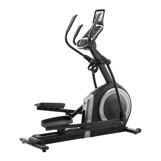
USER'S MANUAL
Model No. NTEL05917.2
Serial No.
Write the serial number in the space
above for reference.
Serial Number
Decal
ACTIVATE YOUR
WARRANTY
To register your product and
activate your warranty today,
go to my.nordictrack.com.
CUSTOMER CARE
For service at any time, go to
nordictrackservice.com.
Or call 1-800-TO-BE-FIT
(1-800-862-3348)
Mon.–Fri. 6 a.m.–6 p.m. MT
Sat. 8 a.m.–12 p.m. MT
Please do not contact the store.
CAUTION
Read all precautions and
instructions in this manual before
using this equipment. Keep this
manual for future reference.
Advertisement
Table of Contents


Need help?
Do you have a question about the NTEL05917.2 and is the answer not in the manual?
Questions and answers