Toa N-8050DS Installation Manual
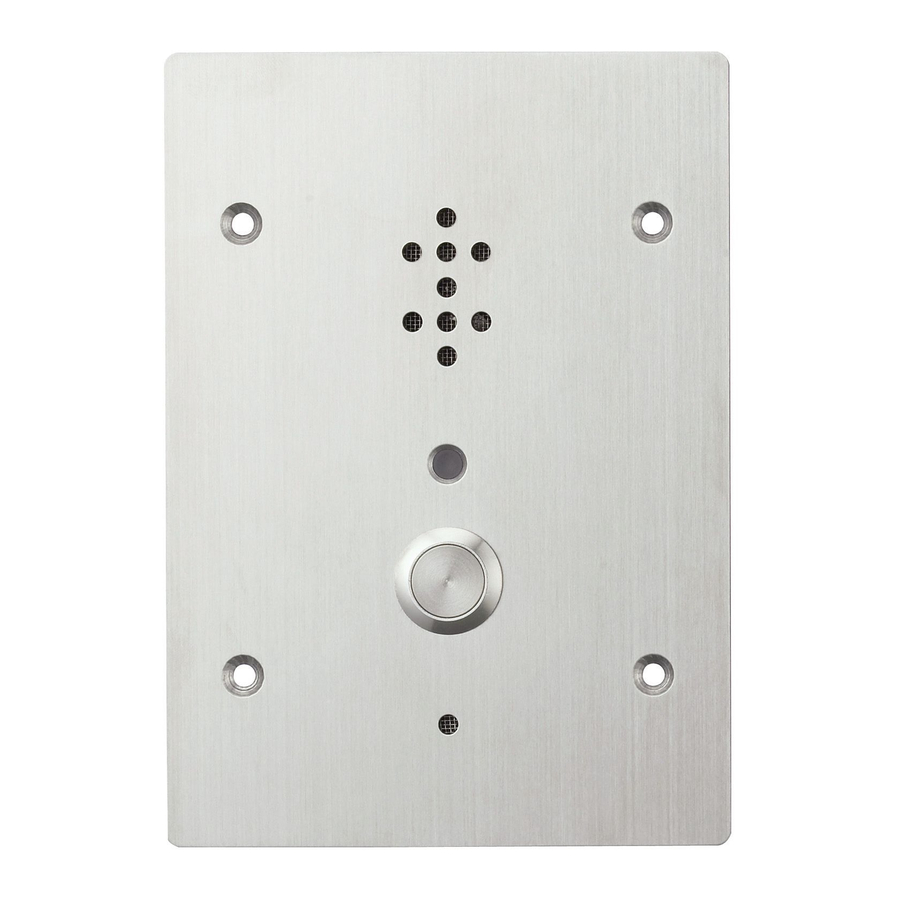
Door station
Hide thumbs
Also See for N-8050DS:
- Installation manual (2 pages) ,
- Specifications (1 page) ,
- Operating instructions manual (269 pages)
Table of Contents
Advertisement
Quick Links
DOOR STATION
1. GENERAL DESCRIPTION
Designed to connect to the IP Intercom Exchange, the
N-8050DS is a door station featuring high quality hands-free
conversation and has a contact output (momentarily closed)
to remotely control an electronic door lock.
Using with an electrical box or surface mounting box, the
station can be mounted to a wall.
The N-8050DS is in full conformity with IP54 water-proof and
dust-proof standards. The operating temperature range is –10
to +50°C.
As provided with guard nets inside to cover over the openings
of microphone and speaker, the N-8050DS can be installed
free from care in public space.
2. WALL MOUNTING
2.1. Mounting to a 3-gang Switch Box (with cover)
Mount the N-8050DS to electrical
boxes mounted in the wall.
Acoustic material (accessory)
Note
Lay it down along the inside
of the box.
N-8050DS
Oval head combination screw
M4 x 25 (accessory)
Notes
• The wall should be over 12 mm thick, and the opening in the
wall for an electrical box should be under 115 mm (wide) by
162 mm (high).
• When using for electronic door lock control, fix the
N-8050DS with tamper-proof screws such as "Torx" screws
to prevent it from being easily removed.
• Be sure to ground the electrical box.
Accessory screws
The N-8050DS comes with 2 types of screws: oval head
combination screw M4 x 25 and oval head combination screw
UNC No.6 x 18. For the electrical box provided with unified
threads, use the oval head combination screws UNC No.6 x 18.
2.2. Mounting to the YS-13A Wall Mount Box
Install the YS-13A on a wall and mount the station in the same
way as 2.1.
INSTALLATION
MANUAL
N-8050DS
Wall surface
YC-150 Back box (option)
or 3-gang electrical box
Wall
N-8050DS
[Section view]
3. INSTALLATION PRECAUTIONS
• When installing the N-8050DS outdoors
or at locations where it gets wet with
water, tightly seal the panel edges.
Besides, provide a weep hole at the
underside of the mounting box to permit
water to drain off.
• When installing the N-8050DS under
difficult
environmental
such as in coastal areas or at humid
locations, cover the inside of the
N-8050DS with coating. For the coating
method, consult TOA sales office.
4. WIRING
4.1. Connection to the Exchange
Connect the Exchange to the station's LINE terminals via the
E-7000TB Terminal Board as illustrated.
N-8000EX/8010EX Exchange
E-7000TB
Terminal board
LINE H C
N-8050DS (rear panel)
4.2. Connection to an External Relay
N-8000EX/8010EX Exchange
LINE H C
N-8050DS (Rear panel)
Seal the panel edges.
conditions
N-8050DS's
front panel
16 lines
Mini-clamp connector
(Supplied with the
N-8000EX/8010EX)
Both upper and lower
terminals (clip terminals)
are internally connected.
Twisted pair cable
power supply
Diode
Relay
+
-
Open collector output: 30 V DC, 50 mA
External
+24 V DC
GND
Advertisement
Table of Contents

Related Manuals for Toa N-8050DS


Summary of Contents for Toa N-8050DS
- Page 1 Using with an electrical box or surface mounting box, the station can be mounted to a wall. 4.1. Connection to the Exchange The N-8050DS is in full conformity with IP54 water-proof and dust-proof standards. The operating temperature range is –10 Connect the Exchange to the station’s LINE terminals via the to +50°C.
- Page 2 7 mm may be required to take adequate measures. Traceability Information for Europe Note Manufacturer: TOA Corporation Do not solder plate on exposed inner cables when 7-2-1, Minatojima-Nakamachi, Chuo-ku, Kobe, Hyogo, Japan using a stranded wire. Authorized representative: TOA Electronics Europe GmbH Step 2.
Need help?
Do you have a question about the N-8050DS and is the answer not in the manual?
Questions and answers