Table of Contents
Advertisement
Quick Links
10 Sunnen Drive
St. Louis, MO 63143
telephone: 314-678-6336
fax: 314-781-2714
www.wellsbloomfield.com
E. B. C.™ Electronic Brew Control ™
E.B.C.™ brewers are protected under
U. S. Patent # 5, 704,275
Other U. S. and Canadian patents.
75786
p/n 2M-
Rev. C
OWNERS MANUAL
for
LO-PROFILE
E.B.C.™ AIRPOT
BREWERS
Model 1882
with optional
7874 Airpot
643
MODELS
1882
and
1882CA
Includes:
Installation
Use & Care
Servicing
Instructions
04
M643
0503
Advertisement
Table of Contents

Subscribe to Our Youtube Channel
Related Manuals for Bloomfield E. B. C. 1882CA


Summary of Contents for Bloomfield E. B. C. 1882CA
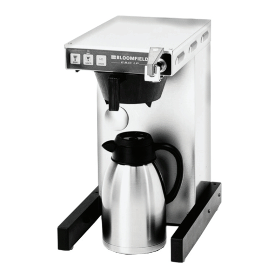
- Page 1 10 Sunnen Drive St. Louis, MO 63143 telephone: 314-678-6336 fax: 314-781-2714 www.wellsbloomfield.com OWNERS MANUAL E. B. C.™ Electronic Brew Control ™ LO-PROFILE E.B.C.™ AIRPOT BREWERS MODELS 1882 1882CA Includes: Installation Use & Care Servicing Instructions Model 1882 with optional 7874 Airpot E.B.C.™...
-
Page 2: Warranty Statement
The prices charged by Bloomfield Industries for its products original installation or eighteen (18) months from the date of are based upon the limitations in this warranty. Seller’s... -
Page 3: Table Of Contents
SPECIFICATIONS Model Style Volts Watts Amps Power Supply Cord 1882 1800 15.0 Airpot 120V NEMA 5-15P 1882CA 1500 12.0 CA = Canadian Standards APPLICABILITY This manual applies to the following Bloomfield Industries E. B. C. products: ® 1882 1882CA... -
Page 4: Features & Operating Controls
FEATURES AND OPERATING CONTROLS Fig. 1 Features & Operating Controls IL2679... -
Page 5: Precautions & General Information
PRECAUTIONS AND GENERAL INFORMATION ELECTRIC SHOCk HAzARD WARNING: All servicing requiring access to non-insulated components must be performed by qualified service personnel. Do not open any access panels which require the use of tools. Failure to heed this warning can result in electrical shock. INjURY HAzARD WARNING: All installation procedures must be performed by qualified personnel with full knowledge of all... -
Page 6: Installation Instructions
The provided water line strainer must be installed in the supply Bloomfield recommends 1/4” line, between the shutoff valve and inlet fitting. Note FLOW copper tubing for installation of arrow marking on strainer body. - Page 7 INSTALLATION INSTRUCTIONS (continued) NSF requires that the brewer be able to be moved for cleaning NOTE: This equipment must underneath. A flex line or loops of copper tubing will satisfy this be installed to comply with requirement. See Figure 2 below. applicable federal, state and local plumbing codes and COPPER LOOPS OR...
-
Page 8: Operation
OPERATION FAUCET OUTLET FAUCET COPPER TUBE SHUT-OFF VALVE FAUCET SUPPLY BRAIDED HOSE FILL TUBE SILICONE IL2684 INLET FITTING Fig. 3 Brewer Operation Diagram IMPORTANT: START-UP For initial start-up, or if the brewer has not been used for an Tank must be full of water extended period of time: before pressing POWER key “on”. - Page 9 OPERATION (continued) WATER HEATER Water temperature is sensed by an electronic water temperature probe inserted into the water tank. This temperature signal is fed to the controller. The setpoint temperature is adjustable. The controller sends a command signal to the power board based upon a comparison between the setpoint temperature and actual temperature.
-
Page 10: Brewing Coffee
BREWING COFFEE A. PREPARATION CAUTION: BURN HAzARD Place one (1) genuine Bloomfield Exposed surfaces paper filter in the brew chamber. of the brewer, brew Add a pre-measured amount of chamber and airpot may be fresh coffee grounds. Gently shake HOT to the touch, and can... -
Page 11: Cleaning Instructions
CLEANING INSTRUCTIONS PROCEDURE: Clean Coffee Brewer CAUTION: BURN HAzARD PRECAUTIONS: Disconnect brewer from electric power. Allow brewer to cool. Brewing and serving temperatures of coffee are Daily extremely hot. FREqUENCY: Hot coffee will cause Mild Detergent, Clean Soft Cloth or Sponge serious skin burns. -
Page 12: Troubleshooting Suggestions
Repair/replace as needed Coffee level too high or low Timer out of adjustment Adjust controller Too many filter papers or wrong Use one (1) genuine Bloomfield filter filter paper per brew Brew chamber dispense hole Brew chamber overflows Thoroughly clean brew chamber... -
Page 13: Servicing Instructions
SERVICING INSTRUCTIONS ACCESS PANELS CAUTION: ELECTRIC SHOCK TOP PANEL: HAzARD Remove top panel to access hot water tank, thermo probe, heating elements, brew circuit tubing, faucet valve and piping. Opening access panels or Top panel is held by two screws at the front and a retaining lip at removing warmer plates on this the rear. - Page 14 SERVICING INSTRUCTIONS (continued) TEMPERATURE ADJUSTMENT CAUTION: Unplug power cord or turn circuit breaker OFF. Remove top ELECTRIC SHOCK panel. Remove button plug from front panel. HAzARD These procedures involve exposed electrical circuits. REMOVE PLUG, These procedures are to INSERT DIAL-TYPE THERMOMETER be performed by qualified IN HOLE...
- Page 15 SERVICING INSTRUCTIONS (continued) IMPORTANT: Water pressure SOLENOID TIME ADJUSTMENT The amount of water dispensed automatically during a brew cycle must be between 20 p.s.i and is controlled by the SOLENOID TIME section of the controller. 90 p.s.i. flowing pressure. If water pressure exceeds this Place empty airpot under brew chamber.
- Page 16 SERVICING INSTRUCTIONS (continued) SOLENOID REPLACE SOLENOID STRAINER Unplug power cord. Turn OFF and disconnect water supply from (note orientation DO NOT REVERSE) brewer inlet fitting. WASHER INLET Remove front panel. Remove two screws holding access door in FITTING place. Remove access door and solenoid. Unscrew inlet fitting cap to release solenoid from door.
- Page 17 SERVICING INSTRUCTIONS (continued) KEYPAD REPLACE CONTROLLER RIBBON Unplug power cord OFF. CABLE Remove front panel. Remove timer faceplate. Disconnect keypad ribbon cable (note position “1”), temperature probe and TEMP power board cable. PROBE POWER Reassemble in reverse order. Be sure all jumpers are remove BOARD from the replacement controller.
-
Page 18: Deliming Instructions
SERVICING INSTRUCTIONS (continued) PROCEDURE: Delime the Water Tank CAUTION: CHEMICAL BURN PRECAUTIONS: Disconnect brewer from electric power. HAzARD Allow brewer to cool. Deliming chemicals may be caustic. FREQUENCY: As required (Brewer slow to heat) Wear appropriate protective TOOLS: Deliming Solution gloves and goggles during this Protective Gloves, Goggles &... - Page 19 Make sure the gasket is properly in place, hoses do not need to be then reinstall lid clamps. delimed. Should deliming hoses become necessary, Bloomfield 8. Reinstall wiring to heating element and thermostat. recommends replacing the Reassemble piping for the faucet. Verify that all internal hoses.
-
Page 20: Exploded View & Parts List
MODEL 1882: EXPLODED VIEW & PARTS LIST... - Page 21 MODEL 1882: EXPLODED VIEW & PARTS LIST (continued) Item Part No. Description Item Part No. Description 2P-70053 PLUG, BUTTON 2” 2I-72215 GASKET, SPRAYHEAD 2C-70107 WASHER, FAUCET, SEMS 7/16EXT NUT KEPS 6-32 LRG Ni 2V-70104 TUBE, WATER INLET SCREW SLT RND 8-32 x 1-1/8 2I-70147 GASKET TANK COVER 2A-43201...
- Page 22 EXPLODED VIEW & PARTS LIST (continued) IL2689 SERVICE KITS; FAUCET REPAIR KITS WS-82573 Handle (item 12a) WS-82575 Seat Cup (item 12c) Faucet Repair kit (Includes 12a Handle, 12c Seat Cup, 12d Spring, 12h Stem, 12j WS-82576 Pin & 12k Bonnet WS-82682 Retainer Clip (item 12b) WS-84804...
-
Page 23: Wiring Diagrams
WIRING DIAGRAM M O D E L V O LT S W ATT S AM P S 188 2 1800 15.0 188 2C A 1500 12.5... - Page 24 10 Sunnen Drive, St. Louis, MO 63143 telephone: 314-678-6336 fax: 314-781-2714 www.wellsbloomfield.com...
Need help?
Do you have a question about the E. B. C. 1882CA and is the answer not in the manual?
Questions and answers