Phocos Any-Grid PSW-H-6.5kW-120/48V & PhocosLink Cloud Quick Start Manual
Hide thumbs
Also See for Any-Grid PSW-H-6.5kW-120/48V & PhocosLink Cloud:
- User and installation manual (58 pages) ,
- Quick start manual (6 pages) ,
- Setup manual (5 pages)

Related Manuals for Phocos Any-Grid PSW-H-6.5kW-120/48V & PhocosLink Cloud


Summary of Contents for Phocos Any-Grid PSW-H-6.5kW-120/48V & PhocosLink Cloud
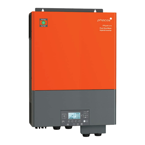
- Page 1 Quick Start Guide Any-Grid PSW-H-6.5kW-120/48V & PhocosLink Cloud English For further languages see Für weitere Sprachen siehe Pour autres langues voir Para otros idiomas ver 对于其他语言请参阅 www.phocos.com...
- Page 2 Experience real-time monitoring of your unit’s performance with the PhocosLink Mobile App. And for ultimate control, add the Phocos Any-Bridge™ AB-PLC or AB-PLC-CAN Monitoring & Control Internet Gateway to remotely monitor your unit from anywhere in the world via a web browser.
-
Page 3: Get Started
Unscrew the four screws that hold the faceplate in place and remove it. Step 2 Assemble the extension box and attach it to the wall in the same location as the faceplate, using screws. Next, install the cable glands. www.phocos.com... - Page 4 Step 1 Remove the bottom cover by unscrewing the five screws and sliding it down. Total weight: 40 lbs IP rating: IP21 Mounting Location: Indoor only Step 2 Use four M4 screws to securely attach the unit to the wall. www.phocos.com...
- Page 5 Bat+ Bat- L N PE L N PE DC SPD Grid/Gen Loads PV2+ PV1+ PV2- PV1- AC SPD BATTERY IMPORTANT: Example only. Actual wiring may differ based on AC INPUT specific system details and local electric code. Breaker LOAD www.phocos.com...
- Page 6 L and N wires, into the lugs. 3. Route the wires through the left cable 3. Route the wires through the left cable gland to ensure a secure and organized gland to ensure a secure and organized installation. installation. www.phocos.com...
-
Page 7: Connecting The Battery
Wiring AC Wire Sizes and Torque Values Unless local code requires otherwise, Phocos advises using copper conductors that are #6 AWG THHN or larger and rated for a minimum of 75°C. Wire Size Torque lbf-in #14 to #10 2.5 to 6... - Page 8 • Short-circuiting the PV+ to the PV- terminal or to the metal body of the unit. • Connecting the wrong polarity. • Connecting the positive or negative terminal of PV1 input with PV2 input. Repeat the two steps below for each PV input. www.phocos.com...
- Page 9 4. AC Output Step 5 To power your critical loads, press the ON/OFF switch on the display module (as described in STEP 3) to activate the AC OUTPUT of the inverter. Congratulations on completing commissioning for single unit systems! www.phocos.com...
-
Page 10: Adjusting Settings
USB-OTG Closed Loop RS485/CAN Relay Control Remote Serial Display RS232 Connector Parallel Parallel Analog Digital Communication** Communication* *Always required for synchronization between multiple units. ** Only required for multiple units on the same phase. www.phocos.com... - Page 11 5. Set menu number 28 to ‘2P1’ (instead of defaults ‘SIG’) 6. Switch OFF the PV and AC breakers and wait for the unit and display to shut down. 7. Repeat steps 3 to 6 on the second inverter (unit 2). www.phocos.com...
- Page 12 9. Quickly switch ON the AC input breaker of each unit. The displays BATTERY AC SPD will show the following. AC INPUT Breaker LOAD IMPORTANT: Example only. Actual wiring may differ UNIT 1 based on specific system details and local electric code. UNIT 2 www.phocos.com...
- Page 13 RS232 ports on each your smartphone or tablet. device and power it up. Step 3 Step 4 Connect to the Any-Bridge and follow the Check your email to confirm the invitation and provided ‘SETUP’ instructions. then log in to www.cloud.phocos.com. www.phocos.com...
- Page 14 APAC Germany India China Phocos Americas, Inc. Phocos AG Phocos India Solar Pvt Ltd. Phocos China Ltd. 325 S. Euclid Ave., Ste. 101 Magirus-Deutz-Str. 12 Plot No. 201 - 203, 231 & 233 Room 1304, Qingdao Interna- Tucson, AZ 85719 USA...
Need help?
Do you have a question about the Any-Grid PSW-H-6.5kW-120/48V & PhocosLink Cloud and is the answer not in the manual?
Questions and answers