
Related Manuals for Ingersoll-Rand P1.5IU-A9


Summary of Contents for Ingersoll-Rand P1.5IU-A9
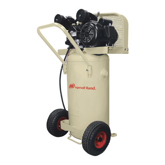
- Page 1 80444425 Revision D December 2020 Models P1.5IU-A9 & P1.5IU-A9-H Owner’s Manual Owner’s Manual Manual del usuario Manuel de l’utilisateur Save These Instructions...
-
Page 2: Table Of Contents
CONTENTS OPERACIÓN ......... 21 „... -
Page 3: Safety
SAFETY „ DEFINITIONS WARNING WILL cause DEATH, SEVERE DANGER HAZARDOUS VOLTAGE - Can cause serious injury or death. INJURY or substantial property Disconnect power and bleed pressure from tank before damage. servicing. Lockout/Tagout machine. Compressor must be CAN cause DEATH, SEVERE connected to properly grounded circuit. -
Page 4: Installing The Air Inlet Filter
„ INSTALLING THE AIR INLET FILTER „ ELECTRICAL WIRING & GROUNDING WARNING CAUTION Any electrical installation and service required should be Do not operate without air inlet filter. performed by a qualified electrician who is familiar with all Install the air inlet filters at the inlet connections at the bare pump. If applicable local, state and federal laws and regulations. -
Page 5: Compressor Lubrication
EXTENSION CORDS - It is preferable to use extra air hose instead COMPRESSOR PUMP FILLING PROCEDURES: of an extension cord to avoid voltage drop and power loss to the motor, and to prevent overheating. If an extension cord must be WARNING used, ensure it meets the following criteria: HAZARDOUS VOLTAGE - Can cause serious injury or death. -
Page 6: Operation
OPERATION „ GENERAL „ SHUTDOWN Your air compressor was designed for 100% continuous duty 1. Set the pressure switch lever to “OFF”. operation with the use of All Season Select synthetic compressor 2. Close the service valve fully. lubricant and 60% continuous duty operation with the use of petroleum lubricant. -
Page 7: Maintenance
MAINTENANCE „ FILTER REPLACEMENT WARNING 1. Unscrew and remove the wing nut (A). Unplug the unit and release air pressure from the tank before 2. Remove the filter cover (B) and element (C) from the base (D). performing maintenance. 3. Install a new element and reassemble the filter assembly. WARNING Filter Replacement Wear appropriate personal safety equipment such as safety... -
Page 8: Belt Adjustment
„ BELT ADJUSTMENT „ TANK INSPECTION CHECKING BELT TENSION - Check belt tension occasionally, The life of an air receiver tank is dependent upon several factors especially if looseness is suspected. A quick check to determine if including, but not limited to, operating conditions, ambient adjustment is proper may be made by observing the slack side of environments, and the level of maintenance. -
Page 9: Troubleshooting
TROUBLESHOOTING PROBLEM POSSIBLE CAUSE POSSIBLE SOLUTION Lubricant viscosity too low. Drain existing lubricant and refill with proper lubricant. Lubricant level too low. Add lubricant to crankcase to proper level. Detergent type lubricant being used. Drain existing lubricant and refill with proper lubricant. Abnormal piston, ring Cylinder(s) or piston(s) scratched, worn or Repair or replace as required. - Page 10 PROBLEM POSSIBLE CAUSE POSSIBLE SOLUTION Air leaks in air discharge piping. Check tubing and connections. Adjust pressure switch to increase differential, if differential adjustment is provided. Install pressure switch with Pressure switch differential too narrow. differential adjustment feature if differential adjustment is Excessive starting and desired.
- Page 11 PROBLEM POSSIBLE CAUSE POSSIBLE SOLUTION Lubricant viscosity too high. Drain existing lubricant and refill with proper lubricant. Check line voltage and upgrade lines as required. Contact Improper line voltage. electrician. Wiring or electric service panel too small. Install properly sized wire or service box. Contact electrician. Poor contact on motor terminals or starter Ensure good contact on motor terminals or starter connections.
-
Page 12: Parts List
PARTS LIST EN-12 80444425 Rev. D... - Page 13 80444425 Rev. D EN-13...
- Page 14 EN-14 80444425 Rev. D...
- Page 15 80444425 Rev. D EN-15...
-
Page 16: Repair Kits
„ REPAIR KITS P1.5IU-A9 DESCRIPTION KIT CCN KIT COMPOSITION (2) CYLINDER GASKET — PART NO. 23191901 (1) REAR BEARING SEAT GASKET — PART NO. 23192016 GASKET KIT 42665463 (2) CYLINDER HEAD GASKET — PART NO. 23192040 (2) VALVE SEAT GASKET — PART NO. 23213051... -
Page 17: Warranty
WARRANTY Retain your receipt as proof of purchase in the event of a claim under warranty. Questions? Parts? Service? 1-800 AIR SERV Visit our website: ingersollrandproducts.com 80444425 Rev. D EN-17... -
Page 18: Seguridad
Puede causar lesiones graves o la muerte. Los compresores de aire Ingersoll-Rand no están AIRE DE ALTA PRESIÓN - La derivación, modificación o retiro diseñados, ni destinados para aire respirable. No se debe de las válvulas de seguridad/alivio puede causar lesiones... -
Page 19: Instalación Del Filtro De Entrada De Aire
La toma debe usarse con un conectador instalado y conectado a tierra según todos loas códigos y regulaciones locales. Si usa el lubricante sintético Ingersoll-Rand para compresores, Las configuraciones del conector y del enchufe deben ser idénticas. todo el material de la tubería descendente y los componentes NO USE UN ADAPTADOR. -
Page 20: Lubricación Del Compresor
LUBRICANTE SINTÉTICO - Se recomienda usar el Lubricante sintético Ingersoll-Rand para compresores desde el inicio de las operaciones. Consulte la sección de GARANTÍA para obtener información respecto a la garantía ampliada. -
Page 21: Operación
El compresor fue diseñado para funcionar a un régimen continuo 1. Ponga la palanca del disyuntor neumático en la posición “OFF”.. de 100% con el uso el lubricante sintético Ingersoll-Rand para 2. Cierre la válvula de servicio completamente. compresores y un régimen continuo de 60% con el uso de otros lubricantes de petróleo. -
Page 22: Mantenimiento
MANTENIMIENTO „ REEMPLAZO DEL FILTRO ADVERTENCIA 9. Destornille y saque la tuerca de mariposa (A). Desconecte el compresor y descargue la presión del tanque 10. Saque la cubierta del filtro (B), el deflector (C) y el elemento (D) antes de ejecutar el mantenimiento. de la base(E). -
Page 23: Ajuste De La Correa
útil del estanque es difícil de predecir; por de la correa cuando la unidad está en operación. Si hay un leve arco, lo tanto, Ingersoll-Rand le recomienda programar una inspección por lo común la correa está satisfactoriamente ajustada. -
Page 24: Localización De Fallas
LOCALIZACIÓN DE FALLAS PROBLEMA CAUSA POSIBLE SOLUCIÓN POSIBLE Lubricante poco viscoso. Drene el lubricante y vuelva a llenar con uno adecuado Muy poco lubricante. Agregue lubricante al cárter hasta el nivel adecuado. Se está usando lubricante tipo detergente. Drene el lubricante y vuelva a llenar con uno adecuado. Desgaste anormal del Cilindros o pistones rayados, gastados o Repare o reemplace según sea necesario. - Page 25 PROBLEMA CAUSA POSIBLE SOLUCIÓN POSIBLE Válvulas del compresor rotas, carbonizadas, Inspeccione las válvulas. Limpie o reemplace según sea sueltas o con filtraciones. necesario. Instale el Juego de válvulas. Limpie el o los pistones. Repare o reemplace según sea Acumulación de carbono sobre el o los pistones. necesario.
- Page 26 PROBLEMA CAUSA POSIBLE SOLUCIÓN POSIBLE Humedad en el cárter Se está usando lubricante tipo detergente. Drene el lubricante y vuelva a llenar con uno adecuado. o apariencia “lechosa” Ciclos de operación muy cortos. Opere el compresor con ciclos de operación más largos. en el lubricante de petróleo o herrumbre Compresor ubicado en área húmeda o mojada.
-
Page 27: Parts List
PARTS LIST 80444425 Rev. D ES-27... - Page 28 ES-28 80444425 Rev. D...
- Page 29 80444425 Rev. D ES-29...
- Page 30 ES-30 80444425 Rev. D...
-
Page 31: Repair Kits
„ REPAIR KITS P1.5IU-A9 DESCRIPTION KIT CCN KIT COMPOSITION (2) CYLINDER GASKET — PART NO. 23191901 (1) REAR BEARING SEAT GASKET — PART NO. 23192016 GASKET KIT 42665463 (2) CYLINDER HEAD GASKET — PART NO. 23192040 (2) VALVE SEAT GASKET — PART NO. 23213051... -
Page 32: Garantia
GARANTIA Guarde su recibo para las demandas de la garantía. ¿Preguntas? Piezas? Servicio? 1-800 AIR SERV Visite nuestro sitio web: ingersollrandproducts.com ES-32 80444425 Rev. D... -
Page 33: Sécurité
SÉCURITÉ „ DÉFINITIONS AVERTISSEMENT OCCASIONNERA la MORT, des DANGER TENSION DANGEREUSE - . Elle peut causer des blessures BLESSURES SÉVÈRES ou des graves ou la mort. Débrancher l’alimentation avant réparer. dégâts matériels considérables. Verrouiller/étiqueter la machine. Le compresseur doit être POURRA occasionner la MORT, branché... -
Page 34: Refoulement
Acceptable: ATTENTION Viton®, Teflon®, époxydes (chargés à la fibre de verre), alkydes résistants aux Ne pas faire fonctionner l’appareil à une température huiles, fluorosilicones, hydrocarbures fluorés, polysulfides, uréthannes à 2 inférieure à -6,6 °C (20 °F) ou supérieure à 51,0 °C (125 °F). composants, nylon, Delrin®, Celcon®, caoutchoucs à... -
Page 35: Lubrification Du Compresseur
seulement des agents antirouille, antioxydants et antimousse, AVERTISSEMENT que son point d’éclair soit de 227 °C (440 °F) ou plus et que sa température d’inflammation spontanée soit de 343 °C (650 °F) ou Dans le cas d’une secousse en fournissant une sortie pour plus. -
Page 36: Opération
OPÉRATION REMARQUE - Si la pression du réservoir se diminue au-dessous du „ GÉNÉRALITÉS minimum préétabli en usine, le pressostat se remet à zéro et relance Ce compresseur d’air est conçu pour un service continue de 100% en le compresseur. utilisant le lubrifiant synthétique Ingersoll Rand pour compresseurs et pour un service continue de 60% en utilisant un lubrifiant à... -
Page 37: Entretien
ENTRETIEN „ REMPLACEMENT DU FILTRE AVERTISSEMENT 1. Dévisser et retirer l’écrou à ailettes (A). Débrancher le compresseur et purger la pression d’air avant 2. Retirer le capot du filtre (B) et l’élément filtrant (C) de la base (D) d’effectuer l’entretien. 3. -
Page 38: Ajustement De La Courroie
„ AJUSTEMENT DE LA COURROIE „ INSPECTION DU RÉSERVOIR VÉRIFICATION DE LA TENSION - Vérifier occasionnellement la La longévité du réservoir accumulateur d’air dépend de plusieurs tension de la courroie, particulièrement si elle semble lâche. Pour facteurs, y compris, sans s’y restreindre, les conditions d’exploitation, une vérification rapide, observer si le brin mou de la courroie est le milieu ambiant et le niveau d’entretien. -
Page 39: Dépannage
DÉPANNAGE PROBLÈME CAUSE POSSIBLE SOLUTION POSSIBLE Vidanger le lubrifiant actuel et le remplacer par un lubrifiant Viscosité trop faible du lubrifiant. qui convient. Verser du lubrifiant dans le carter principal jusqu’au niveau Niveau de lubrifiant trop faible. requis. Vidanger le lubrifiant actuel et le remplacer par un lubrifiant Le lubrifiant utilisé... - Page 40 PROBLÈME CAUSE POSSIBLE SOLUTION POSSIBLE Verser du lubrifiant dans le carter principal jusqu’au niveau Niveau de lubrifiant trop faible. requis.. Fuites, bris ou accumulation de calamine dans Inspecter les clapets. Les nettoyer ou les remplacer au les clapets du compresseur. besoin.
- Page 41 PROBLÈME CAUSE POSSIBLE SOLUTION POSSIBLE Humidité dans le Vidanger le lubrifiant actuel et le remplacer par un lubrifiant Le lubrifiant utilisé est du type à détergent. carter principal ou qui convient. aspect laiteux du Cycles de marche extrêmement légers. Faire fonctionner le compresseur par cycles plus longs. lubrifiant à...
-
Page 42: Parts List
PARTS LIST FR-42 80444425 Rev. D... - Page 43 80444425 Rev. D FR-43...
- Page 44 FR-44 80444425 Rev. D...
- Page 45 80444425 Rev. D FR-45...
-
Page 46: Repair Kits
„ REPAIR KITS P1.5IU-A9 DESCRIPTION KIT CCN KIT COMPOSITION (2) CYLINDER GASKET — PART NO. 23191901 (1) REAR BEARING SEAT GASKET — PART NO. 23192016 GASKET KIT 42665463 (2) CYLINDER HEAD GASKET — PART NO. 23192040 (2) VALVE SEAT GASKET — PART NO. 23213051... -
Page 47: Garantie
GARANTIE Gardez votre reçu pour des réclamations de garantie. Questions ? Pièces ? Service ? 1-800 AIR SERV Visiter notre site de web : ingersollrandproducts.com 80444425 Rev. D FR-47... - Page 48 ingersollrandproducts.com © 2020 Ingersoll Rand...
Need help?
Do you have a question about the P1.5IU-A9 and is the answer not in the manual?
Questions and answers