Table of Contents
Advertisement
Quick Links
Advertisement
Table of Contents

Related Manuals for CAME GARD G3000


Summary of Contents for CAME GARD G3000
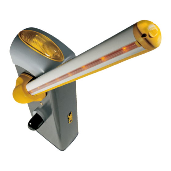
- Page 1 QUICK ROAD BARRIERS INSTALLATION MANUAL G3000 - G3000I English...
-
Page 2: Table Of Contents
Index Legend of symbols p. 4 Intended use and limits to use p. 4 Intended use p. 4 Limits to use p. 4 Description p. 4 Technical data p. 4 Description of parts p. 5 Dimensions p. 6 Installation p. 6 Preliminary checks p. - Page 3 Warning Sings (e.g. gate plate). (i.e. that for which it was expressly built for). Any other use is Special instructions and to be considered dangerous. Came Cancelli Automatici S.p.A. advice for users is not liable for any damage resulting from improper, wrongful •...
-
Page 4: Legend Of Symbols
Intended use and limits to use Intended use The G3000 barrier is designed and built by © CAME Cancelli Automatici S.p.A. in compliance with current regulations on safety concerning the use of parking facilities in private, public, residential and areas with high fl ow densities. -
Page 5: Description Of Parts
Description of parts Upper dome ZL30 Control panel Transmission shaft plate Transformer Cabinet Lever activated gearmotor release Inspection hatch Counter-balancing spring Gearmotor Gearmotor release with customised key Lever arm Hatch lock with customised key Limit-switch assembly Power switch ACCESSORIES Semi-eliptical arm complete with impact-proof profile, luminous cord, cord connecting cable and red adhesive strips Ø60 mm tube arm complete with red reflective adhesive strips Semi-eliptical arm attachment flange complete with flange cover and arm end-caps Ø60 mm tube-arm attachment flange complete with flange cover and arm end-caps... -
Page 6: Dimensions
Dimensions max. 2750 Installation Installation must be carried by skilled, qualified technicians in accordance with current regualtions. Preliminary checks Before beginning to install, the following is necessary: Set up proper omnipolar cut-off device, with more than 3mm of distance between contacts, with sectioned power source; •... -
Page 7: Types And Thicknesses Of Cables
Types and thicknesses of cables Type of Cable length Cable length Cable length Connection cable 1 < 10 m 10 < 20 m 20 < 30 m Powered by 120 / 230 V AC 3G x 1.5 mm 3G x 2.5 mm 3G x 4 mm FROR CEI Photocell transmitters... -
Page 8: Preparing The Anchoring Base
Preparing the anchoring base The following illustrations are just examples, in that the space for securing the operator and accessories depends on the overall measurements. It is up to the installer to choose the most suited solution. Dig a pit for the anchoring base and set up the required corrugated tubes for the connections coming out of the... -
Page 9: Installing The Cabinet
Installing the cabinet Warning: the barrier must be mounted by at least two persons. Use proper hoisting equipment when transporting the barrier. During mounting phase, the barrier may be unstable. Do not rest against barrier until fully mounted, to avoid any tumbling over. NOTE: This manual shows mounting operations using a left-hand barrier. -
Page 10: Adjusting The Mechanical Endstops
Adjusting the mechanical endstops N.B.: to do after electrical connections are made to the control panel. Close the inspection hatch and power up the system. Activate the arm to check whether it is parallel to the road surface when close and at about 89° when open. To correct the vertical position (=opening), lower the barrier arm, open the inspection door and rutn the opening mechanical stop either clockwise or counterclockwise, then secure the stop with the counter nut. -
Page 11: Manual Release Of The Barrier Arm
Manual release of the barrier arm - Insert the key into the lock and turn it clockwise. Manually lift the barrier arm and re-lock it by turning the key counter-clockwise. WARNING! The release action may result in danger for the user, when, for whate- ver reason - the arm is improperly fixed to the... -
Page 12: Description Of The Control Panel
Description of the control panel Designed and built by CAME Cancelli Automatici S.p.A. The control - immediate closing; panel is powered by 120 / 230 V AC, at 50 / 60 Hz frequency. - Prefl ashing by the fl ashing light;... -
Page 13: Electrical Connections
Electrical connections Gearmotor, encoder and transformer (only for possible maintenance actions) Shown is the connection for a left-hand barrier. A right-hand barrier has gearmotor cables inverted on terminals M-N. (3.15A - 230V) THERMAL 36V 24V 0 (5A - 120V) line fuse Power switch Power source and accessories Power supply 230 V AC, Frequency 50/60 Hz. -
Page 14: Command Devices
Command devices Stop button (N.C. contact.) - Excludes automatic closing, to resume movement press the command button or tramistter key. N.B.: if contact is unused, select "0" (Deactivated) from the "F 1" function. Opening button (N.O.contact.) this is obligatory with Maintained Action function. -
Page 15: Safety Devices
Safety devices Confi gure the CX or CY contact (N.C.), which is an input for EN 12978 regulation-compliant safety devices such as photocells. Photocells See CX input functions (Function F2) or CY (Function 3) in: - C1 «reopeing when closing», when arm is closing, opening the contact triggers the inversion of movement until it is fully raised - C4 «obstacle waiting», stops the arm if it is moving and resumes movement after obstacle is removed. -
Page 16: Programming
Programming Description of the commands Display The ESC button is for: The ENTER buttons is for: - exiting menus; - accessing the menus; < > ENTER - cancelling any changes. - confirm and memorise the set value. The <> keys are for: to move from one menu item to another;... -
Page 17: Menu Structure
Menu structure - Total stop function - Function associated to CX input - Function associated to CY input - Safety test function - Maintained action function - Command mode on 2-7 - Obstacle detection when motor is idle function F 10 - Indicator light function F 15 - Intermittent luminous cord function... -
Page 18: Functions Menu
A 3 (travel calibration): automatic calibration operation of the gearmotor travel(see "travel calibration" paragraph"). 0 = Deactivated; 1 = Activated. ENTER >...> > ENTER > A 4 (Reset parametres): data restoring procedure (for default settings) and travel calibration cancellation. = 0 = Deactivated; 1 = Activated. ENTER >...>... - Page 19 F 5 (Safety test): allows the card to check the efficienty of safety devices (i.e. photocells) after avery opening or closing command. 0 = Deactivated (by default); 1 = CX; 2 = CY; 3 = CX =+CY ENTER > > >...
- Page 20 F 19 (Automatic closing time): the automatic closing timer activates at the closing endpoint. The preset time can be adjusted, and is anyway conditioned by any triggered safety devices. it deactivated after a total safety "stop" or when the power is cutt off. The waiting time can be deactivated or adjusted from 1"...
- Page 21 F 31 (closing decelerarion speed): setting the speed for closing deceleration, calculated as a percentage. 10 = 10% of motor deceleration speed (minimum); ....15 = 15% of motor deceleration speed (by default); ....30 = 30% of motor deceleration speed (maximum). >...
-
Page 22: Users Menu
Users menu U 1 (Adding user with associated command): adding user (max 25 users) associated to a command, via tramsitter 1 = 1 = step command (open-close); 2 = 2 = sequential commande (open-stop-close-stop); 3 = open only command. ENTER >...>... -
Page 23: Adding User With Associated Command
Adding user with associated command User Asssociated command 1) Select "U 1". Press ENTER to confirm. < > ENTER 2) Use the arrow buttons to select the 10 - command (1=step, 2=sequential, 3=open) to assign to the user. 11 - Press ENTER to confirm... -
Page 24: Motor Test
Motor test Select “A 1”. Press ENTER to confirm. < > ENTER 2) Select 1 to activate the test Press ENTER to confirm... < < < < > > > > ENTER - - - 3) ..."---" will appear on the screen, waiting for a command... -
Page 25: Error Messages And Notifi Cations
c l i 3) The arm will lower to close until the mechanical stop shuts off. < > ENTER o p I 4) ...subsequently, the arm will raise to open until the mechanical stop shuts off. < > ENTER Error messages and notifi cations “Er1”: motor calibration interrupted;... -
Page 26: Safety Instructions
Safety instructions Important general safety instructions This product is only intended to be used for the purpose it was designed. Any other use is therefore improper and dangerous. The manu- facturer is not liable for any damage caused by improper, wrongful or unreasonable use. Stay away from working mechancal parts. -
Page 27: Extraordinary Maintenance
Periodic maintenance log to be done twice yearly by the end-users Date Notes Signature Extraordinary maintenance The following table is used to log extraordinary maintenance, repair and improvement jobs done by the specialised external firms. N.B.: All extraordinary maintenance jobs must be carried out by skilled technicians. Extraordinary maintenance log Installer's stamp Product name... -
Page 28: Troubleshooting
UNI EN ISO 14001 standard to ensure environmental protection. Please help us to safeguard the environment. At CAME we believe this to be one of the fundamentals in its market operations and deve- lopment strategies. Just follow these short disposal instructions: DISPOSING OF THE PACKAGING The components of the packaging (i.e. -
Page 29: Ce Compliance Statement
CE Compliance statement... - Page 30 (+34) 91 52 85 009 127273, Moscow Moscow (+34) 91 46 85 442 (+7) 495 739 00 69 (+7) 495 739 00 69 (ext. 226) CAME United Kingdom Ltd. CAME United Kingdom Ltd. GREAT BRITAIN PORTUGAL CAME Portugal CAME Portugal...
Need help?
Do you have a question about the GARD G3000 and is the answer not in the manual?
Questions and answers