Table of Contents
Advertisement
Quick Links
Advertisement
Table of Contents

Related Manuals for CAME G4040Z


Summary of Contents for CAME G4040Z
- Page 1 Street barriers FA01242-EN G4040Z- G4040IZ INSTALLATION MANUAL EN English...
- Page 2 This happens under his producT should only be used for The purpose for which iT was . caMe s. close supervision or once They have been properly insTrucTed To use The expliciTly designed...
- Page 3 The automatic barrier is designed for private and public parking facilities. Any installation and/or use other than that specified in this manual is forbidden. Limits to use Type G4040Z - G4040IZ Maximum clearance width of the passage (m) 3.75 Technical data...
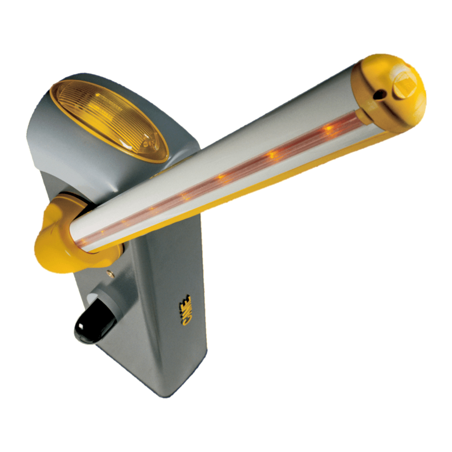
- Page 4 Description of parts 1. Dome 9. Boom setting mechanical stop 2. Motor-shaft plate 10. Lever arm 3. Mid plate 11. Micro-switch housing plate 4. Boom-attachment cover 12. Gearmotor with encoder 5. Protective casing shear proof 13. Inspection hatch 6. Cabinet 14.
- Page 5 GENERAL INSTRUCTIONS FOR INSTALLING ⚠ Only skilled, qualified staff must install this product. Important! Using original CAME control and safety devices and accessories ensures easy installation and system maintenance. Preliminary checks ⚠ Before beginning, do the following: • make sure the plate is anchored to a solid spot;...
-
Page 6: Installation
INSTALLATION ⚠ The following illustrations are mere examples. Consider that the space available in which to fit the barrier and accessories will vary depending on the area where it is installed. It is up to each installer to select the most suitable solution. ⚠... - Page 7 Fill the hole with earth around the concrete block. Remove the nut and washer from the bolts Fit the electric cables into the tubes so that they come out about 600 mm. Preparing the barrier Remove the two screws on the top dome, fit the key into the lock and turn it counter clockwise . Lift the dome and remove the inspection hatch .
- Page 8 Installing the barrier The cabinet should be installed with the inspection hatch on the most accessible side to make any adjusting easier. Place the cabinet onto the anchoring plate and fasten it using nuts and washers. Assemble the boom-attaching cover, the mid plate and motor-shaft plate with a screw. Leave the screw loose to then facilitate fitting the boom. ⚠...
- Page 9 Fit the boom into the boom-attachment cover and fasten it using the screws. UNI5931 M8x12 UNI5931 M8x20 Cut the groove covering frames to the right length and fit them into the boom grooves on either side . Fit the shock-proof frame into the boom and cut off any excess . Fasten the end cap using the screws .
- Page 10 Balancing the boom Before balancing the boom, check on the table below for congruences between the chosen spring, accessories and passage clearance. PASSAGE CLEARANCE 8(max 3.75 m) Spring 001G02040 Ø 40 mm Spring 001G04060 Ø 50 mm Spring 001G06080 Ø 55 mm BOOM LENGTH (m) 1,5 ÷...
- Page 11 Hook the eyelet rod to the anchoring rod . Release the gearmotor and manually turn the spring to increase or reduce traction . The boom should stabilize at 45°. Fasten the counter nut and lock the gearmotor again. Check the proper working state of the spring. With the boom raised vertically the spring is not taut.
-
Page 12: Fuse Table
ELECTRICAL CONNECTIONS AND PROGRAMMING ⚠ Warning! Before working on the control panel, cut off the main current supply and, if present, remove any batteries. Power supply to the control panel and control devices: 24 V AC/DC. The features are set using the DIP switches, the adjustments using the trimmer. All connections are quick-fuse protected. - Page 13 Factory wiring The gearmotor is already connected. To install the barrier on the right, follow the instructions in the PREPARING THE BARRIER paragraph. 24 V DC gearmotor Opening micro Orange switch White Orange Blue Brown Closing micro switch PT F FC FA E +10 -11 1 C1 C5 Warning devices...
- Page 14 DIR photocells DELTA-S Safety devices photocells Configure contact C1 and/or C5 (NC), input for safety devices such as photocells. C1 reopening while closing. When the boom is closing, opening the contact causes its movement to invert until fully opened; If unused, shortcircuit contact 2-C1. C5 immediate closing.
- Page 15 To correct the boom's vertical position: - lower the boom; - open the inspection hatch; - turn the opening mechanical stop clockwise to increase the boom's travel or counter clockwise to reduce it . Fasten the stop with a counter nut . ...
- Page 16 Activating the radio control Connect the RG58 cable antenna cable to the corresponding terminals . For TOP, TAM and TWIN series transmitters with 433.92 MHz frequency, set the AF card jumper as shown in the figure . Fit the AF card into the control board connector . ⚠...
- Page 17 Programming the features Default settings 1 2 3 4 5 6 7 8 9 10 3 4 5 6 7 8 9 10 DIP-SWITCH Description of functions 1 ON AUTOMATIC CLOSING (1 OFF - deactivated) 2 ON ONLY OPEN from button 2-7 and/or from transmitter (with AF card fitted) 2 OFF OPEN-CLOSE-INVERT from the button on 2-7 and/or from a transmitter (with AF card fitted) 3 ON...
-
Page 18: Final Operations
Adjusting speed Min. = minimum Med. = medium Max. = maximum COM = common DIS. 27370 Max. Med. Min. Min. Max. To regulate the travel speed, move faston To adjust the slow-down speed, move A on Min., Med. or Max. faston B to Min. - Page 19 RELEASING THE BOOM ⚠ This procedure must be done with the mains power cut off. Fit the key into the lock and turn it clockwise . Manually raise the boom and lock it back into place by turning the key counter clockwise ...
- Page 20 PAIRED CONNECTION WITH A SINGLE COMMAND Establish the Master barrier and the Slave barrier. MASTER SLAVE On the MASTER barrier's electronic board, make the necessary electrical connections, activate the radio control, program the functions and settings. MASTER 3 4 5 6 7 8 9 10 On the SLAVE barrier's control board, connect the power supply to L-N, the flashing light on 10-E, set DIP switch 7 to ON and adjust the travel and slow-down speeds just like on the MASTER barrier.
-
Page 21: Troubleshooting
Connect the two control boards using terminals RX-TX-GND as shown in the figure. Black Screened cable 2402C 22AWG Black RX TX GND E +10 -11 1 7 C1 C5 SLAVE CONTROL BOARD RX TX GND E +10 -11 1 7 C1 C5 MASTER CONTROL BOARD TROUBLESHOOTING PROBLEM... -
Page 22: Maintenance Log
MAINTENANCE LOG Periodic maintenance ☞ Before doing any maintenance, cut off the power supply, to prevent any hazardous situations caused by accidental boom movements. Periodic maintenance log kept by users (every six months) Date Notes Signature... -
Page 23: Dismantling And Disposal
________________________________________________________________________________________________ DISMANTLING AND DISPOSAL ☞ CAME S.p.A. complies with a certified Environmental Management System at its premises, compliant with the UNI EN ISO 14001 standard to ensure the environment is safeguarded. Please continue safeguarding the environment. At CAME we consider it one of the fundamentals of our operating and market strategies. Simply... - Page 24 CAME S.p.A. Via Martiri Della Libertà, 15 31030 Dosson di Casier - Treviso - Italy tel. (+39) 0422 4940 - fax. (+39) 0422 4941...
Need help?
Do you have a question about the G4040Z and is the answer not in the manual?
Questions and answers